Membrane For a Mems Condenser Microphone

a technology for condenser microphones and membranes, applied in the direction of diaphragm construction, electrostatic transducers of semiconductor transducers, loudspeakers, etc., can solve the problem of certain amount of bending, and achieve the effect of increasing the cross section, reducing the influence of acoustic behavior, and increasing ventilation resistan

Inactive Publication Date: 2008-09-04
KNOWLES IPC M
View PDF2 Cites 37 Cited by
  • Summary
  • Abstract
  • Description
  • Claims
  • Application Information

AI Technical Summary

Benefits of technology

[0026]It is further advantageous when between said first portion, said second portion, and said elements there are slits, which are provided as a gasket. Since the free space between the first area and said elements and between the second area and said elements in principle allows for ventilation, its size should not exceed a certain limit. Said slits in general form a high pass for the arriving sound waves, because slow changes of air pressure are equalized unhindered by said slits, whereas the slits act as a barrier for fast changes. The thinner the slits are the higher the resistance against ventilation is. Therefore the size of the slits may be chosen according a desired characteristic of the membrane or the microphone respectively. Assuming a non rotating membrane, these slits have the same cross section for ventilation over the movement of the membrane. Therefore the fluidic friction within said slits linearly changes with the amplitude of the membrane, as the length of the slits for the ventilating air changes.
[0027]Finally it is advantageous when the maximum amplitude, which the membrane is arranged for, is less than the thickness of the membrane. To avoid a dramatic increase of the cross section of said slits and in turn a significant change of the aforementioned high-pass characteristic, the maximum amplitude of the membrane should not exceed the membrane's thickness. The lower the amplitude in relation to the thickness of the membrane the lower the influence on the acoustic behavior. However the sensitivity of the microphone at a certain frequency depends on the sound pressure anyway, because of the physical context stated before. Assuming that the membrane does not significantly bend when a differential air pressure is applied, the maximum amplitude of the membrane at a certain differential air pressure or a certain sound pressure respectively depends on the stiffness of the elements connecting the first and second area of the membrane.

Problems solved by technology

Applying a differential pressure to a membrane always leads to a certain amount of bending, but for an inventive membrane this is not essential or at least not the only effect.

Method used


Image

  • Membrane For a Mems Condenser Microphone
  • Membrane For a Mems Condenser Microphone
  • Membrane For a Mems Condenser Microphone

Examples


Embodiment Construction

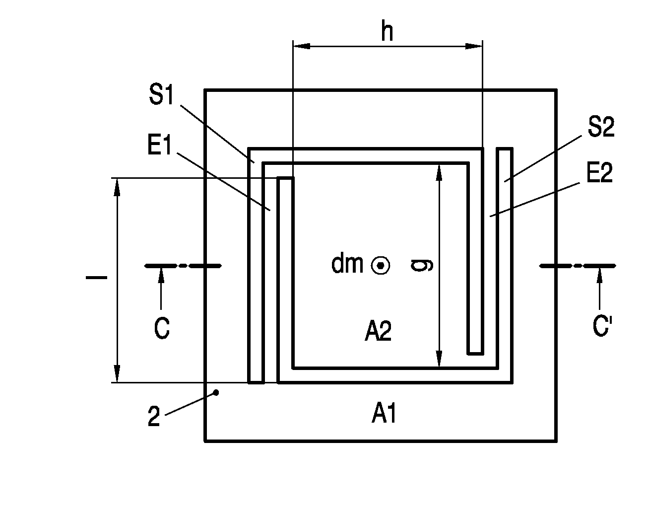
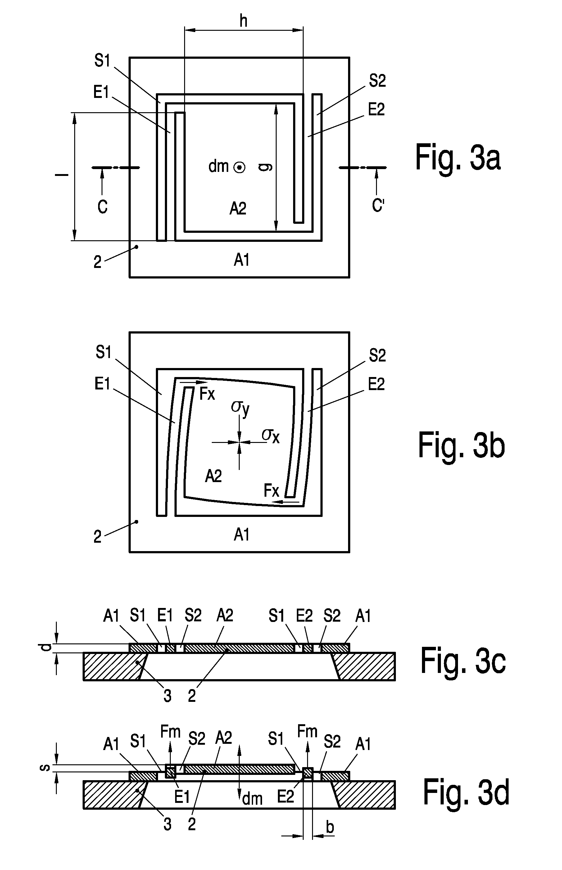
[0045]FIG. 3a shows a top view of a first embodiment of an inventive membrane 2, comprising first portion A1, second portion A2, and two elements E1, E2, having an effective length l, which connect said first A1 and said second portion A2. The two elements E1, E2 are spirally arranged and project counterclockwise from the second portion A2. The second portion A2 has the width g and the length h. The structure is manufactured by etching two U-shaped slits S1 and S2, which free the second portion A2 from the first portion A1 and at the same time form the two elements E1, E2. It can easily be seen that the significant sections of the elements E1, E2 are arranged parallel to the second portion A2. Finally the direction of movement dm is shown in FIG. 1 which normally projects from the planar membrane 2.

[0046]FIG. 3b shows the membrane 2 of FIG. 3a after the etching of the two slits S1, S2 when a planar tensile stress in x-direction σx and in y-direction σy, indicated with arrows, is wit...


PUM


Abstract

A membrane (2) for a microphone (1) is disclosed which comprises a first portion (A1), a second portion (A2), and elements (E1 . . . E4, E1′ . . . E4′), which connect said first (A1) and said second portion (A2). The second portion (A2) is arranged for a movement in relation to said first portion (A1) around an idle position, which movement includes at least a translatory component in a direction of movement (dm) normal to said membrane (2). The elements (E1 . . . E4, E1′ . . . E4′) are provided for definition of a spring constant for said movement around said idle position and are arranged substantially along the outer border of said second portion (A2).

Description

FIELD OF THE INVENTION[0001]The invention relates to a membrane for a microphone comprising a first portion, a second portion, and elements, which connect said first and said second portion, wherein said second portion is arranged for a movement in relation to said first portion in a direction of movement and around an idle position. Moreover the invention relates to a microphone comprising an inventive membrane.BACKGROUND OF THE INVENTION[0002]In principle, a condenser microphone comprises a thin membrane or diaphragm that is mounted in close proximity to a back plate. The thin membrane is fixed at its edges, so that it is able to deflect when sound pressure is acting on it. Together, the membrane and the back plate form an electric capacitor, where the capacitance changes according to said deflection of the membrane. In use, the capacitor will be charged using a DC voltage, usually called polarization or bias voltage. When the capacitance varies due to a varying sound pressure, an...

Claims


Application Information

Patent Timeline
Patent Type & Authority Applications(United States)
IPC IPC(8): H04R19/00
CPCB81B3/0072B81B2201/0257B81B2203/0127H04R2231/003H04R7/18H04R19/005H04R19/04H04R7/04H04R7/02H04R2201/003
Inventor LUTZ, JOSEF
Owner KNOWLES IPC M
Why Eureka
Try Eureka