

Nuclear power plant using nanoparticles in emergency systems and related method
a technology of nuclear power plants and nanoparticles, applied in nuclear elements, nuclear engineering problems, greenhouse gas reduction, etc., can solve the problems of reducing the heat transfer rate of nuclear power plants. , to achieve the effect of increasing the heat transfer ra
- Summary
- Abstract
- Description
- Claims
- Application Information
AI Technical Summary
Benefits of technology
Problems solved by technology
Method used
Image

Examples
Embodiment Construction
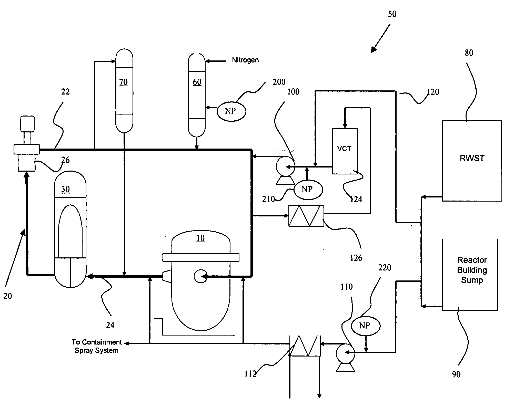
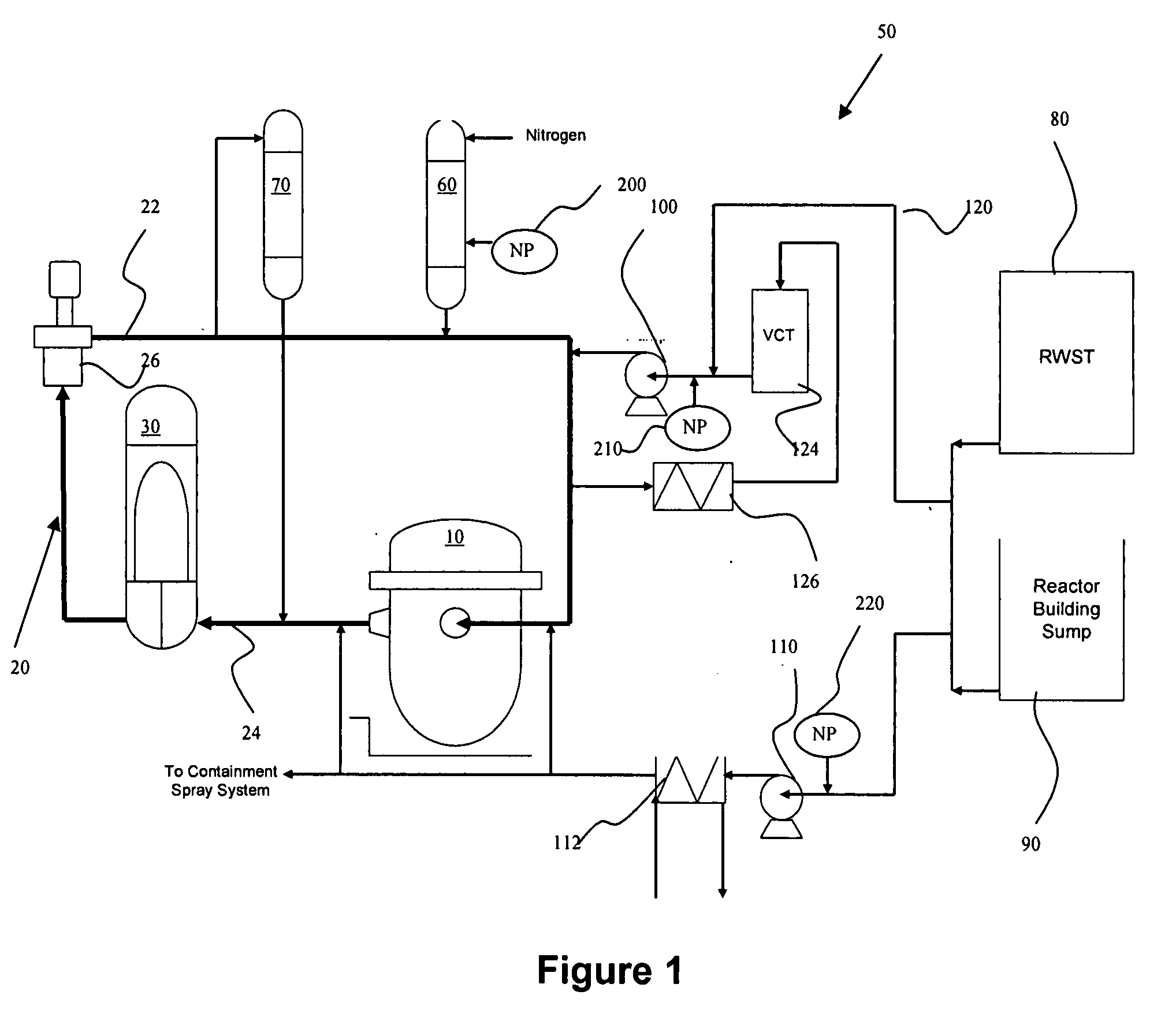
[0029]FIG. 1 shows a nuclear power plant having a reactor 10, a reactor coolant system 20, and an electricity generator 30. In the PWR embodiment shown, electricity generator 30 includes a secondary coolant stream and a turbine. The reactor coolant system 20 includes a cold leg 22 between generator 30 and reactor 10, and a hot leg 24 between reactor 10 and generator 30, as well as a coolant pump 26 in cold leg 22. The reactor coolant system 20 for the PWR embodiment shown also may contains one or more pressurizers 70. In a BWR embodiment, generator 30 typically includes a turbine, and RCS 20 includes a condenser.
[0030]RCS 20 recirculates water during normal operation, and in the preferred embodiment no nanoparticles are added intentionally to the RCS during normal operation, as these can cause issues with the generator and other components.
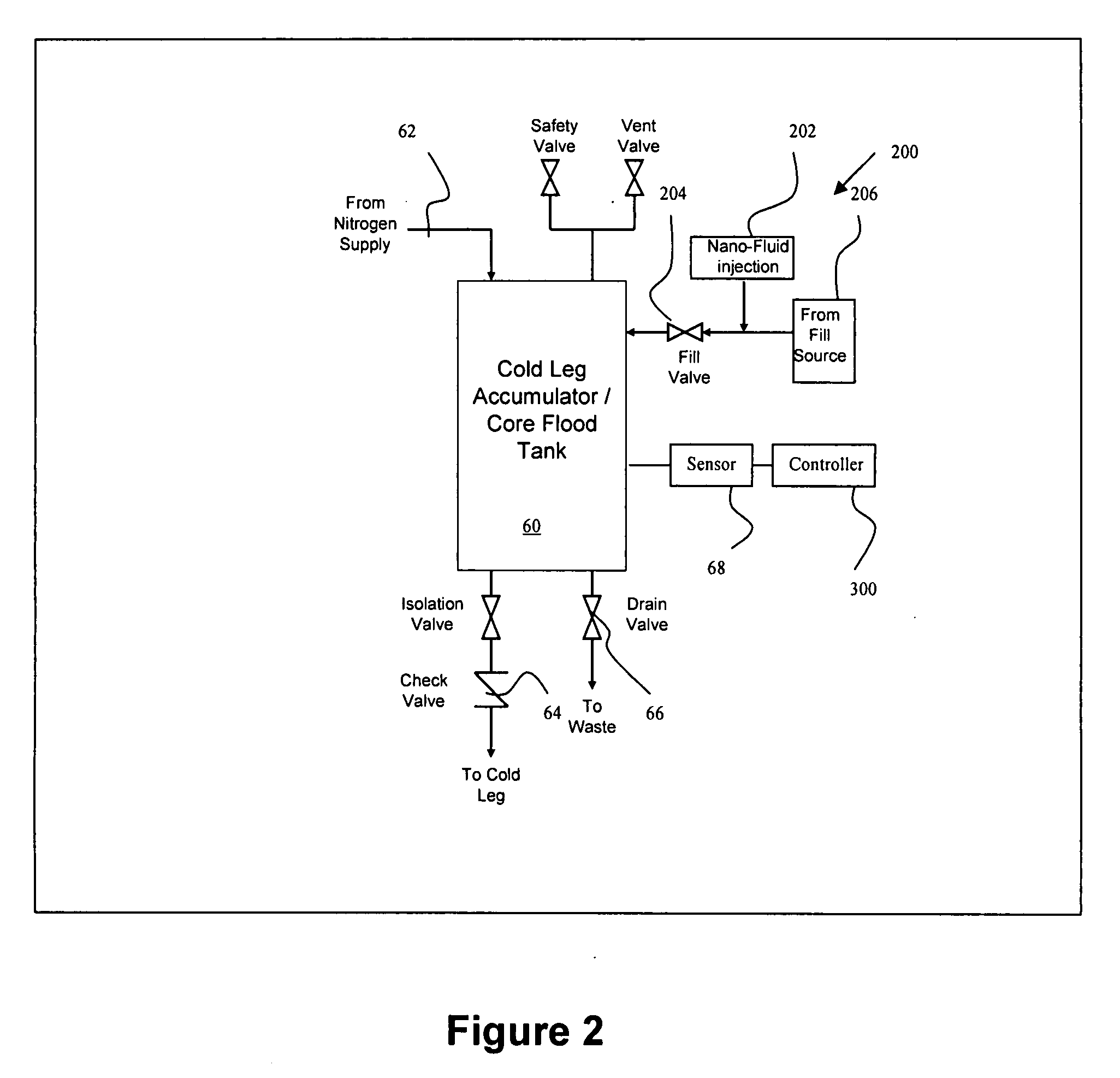
[0031]The nuclear power plant further includes an emergency core cooling system, indicated generally as 50, which includes one or more accumulato...
PUM
 Abstract
Description
Claims
Application Information