

Pellicle frame apparatus, mask, exposing method, exposure apparatus, and device fabricating method
a technology of a reticle and a mask, applied in the field of pellicle frame apparatus, mask, exposing method, exposure apparatus, and device fabricating method, can solve the problem of warping of the reticle, and achieve the effect of high precision and high precision
- Summary
- Abstract
- Description
- Claims
- Application Information
AI Technical Summary
Benefits of technology
Problems solved by technology
Method used
Image

Examples
second embodiment
[0054]Continuing, a second embodiment of the pellicle frame apparatus PF will now be explained, referencing FIGS. 4A and 4B. In contrast to the abovementioned first embodiment, in the second embodiment, a filter member is provided in order to prevent dust from penetrating through the gap S.
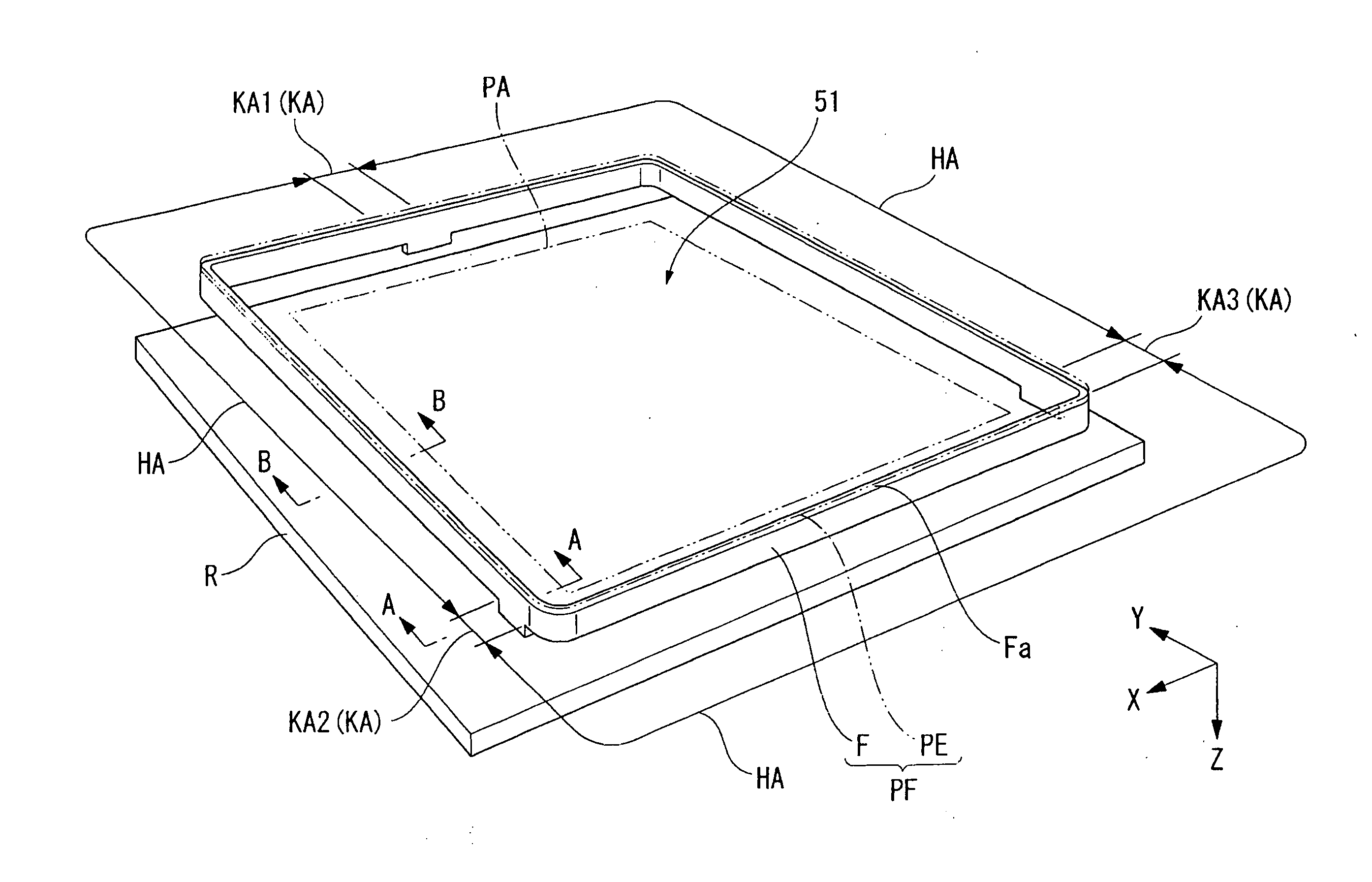
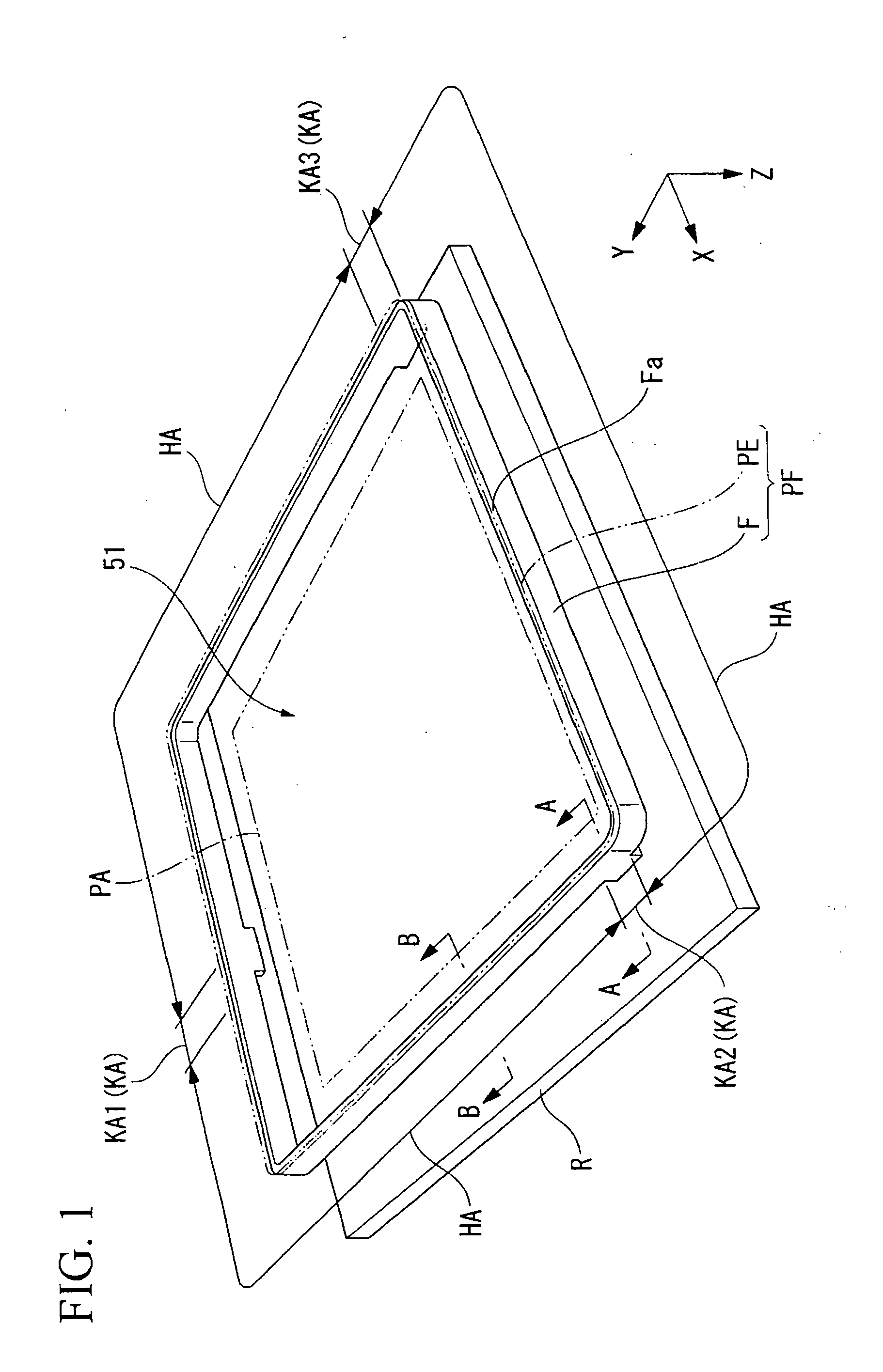
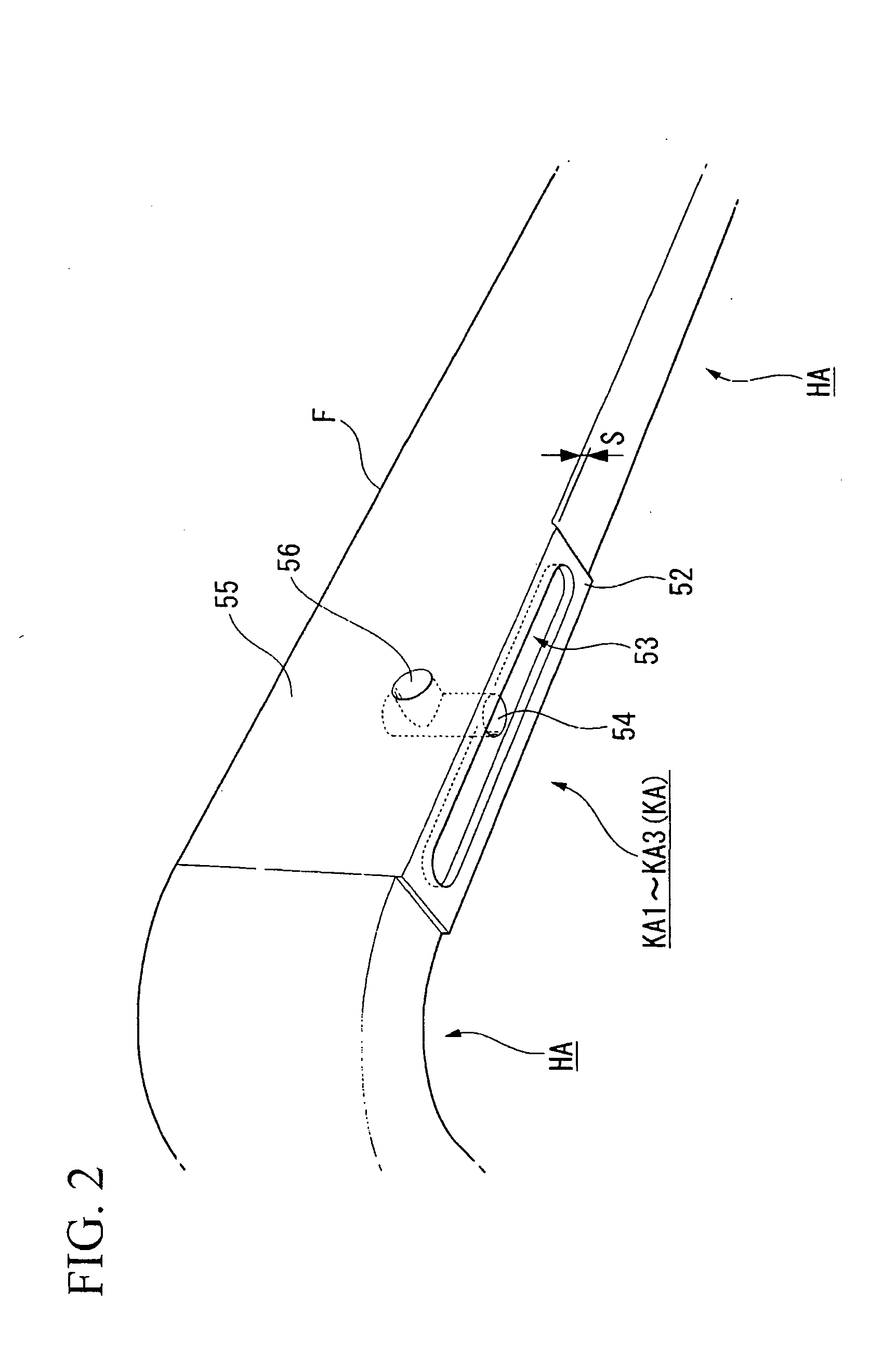
[0055]Elements in the present figure that are identical to constituent elements in the first embodiment shown in FIG. 1 through FIG. 3B are assigned identical symbols, and the explanations thereof are omitted.
[0056]As shown in FIG. 4A, with the pellicle frame apparatus PF of the present embodiment, a sheet shaped filter member (cover member) 60 that covers the gap S is provided by adhering it to the side surface 55 at least at the non-fixed area HA.
[0057]The filter member 60 is porous and has micropores that can capture foreign matter such as dust; for example, a raw material can be used that is a composite of a polyurethane polymer and a film that is fabricated by stretching polytetrafluoroethyle...
third embodiment
[0061]Continuing, a third embodiment of the pellicle frame apparatus PF will now be explained, referencing FIG. 5. The third embodiment differs from the second embodiment in that the configuration of the filter member that prevents the penetration of dust through the gap S is different.
[0062]Furthermore, constituent elements in the present figure that are identical to those in the second embodiment shown in FIGS. 4A and 4B are assigned identical symbols, and the explanations thereof are omitted.
[0063]In the present embodiment, the gap S is filled with a filter member 61.
[0064]A porous member that is capable of venting gas into and out of the frame F, e.g., a sponge member or foam rubber, is used as the filter member 61.
[0065]The present embodiment also obtains advantageous effects that are similar to those of the abovementioned first embodiment, and can prevent the reticle R from conforming to the frame F and warping, even if the flatness of the opposing surface of the frame F, i.e....
fourth embodiment
[0066]Continuing, a fourth embodiment of the pellicle frame apparatus PF will now be explained, referencing FIG. 6 through FIG. 8. Furthermore, constituent elements in the present figures that are identical to those in the first embodiment shown in FIGS. 1-3B are assigned identical symbols, and the explanations thereof are omitted.
[0067]In the pellicle frame apparatus PF of the present embodiment as shown in FIG. 6, the entire surface of the opposing area (the opposing surface) of the frame F that opposes the reticle R contacts the reticle R and is fixed thereto by bonding. Furthermore, the frame F comprises: single body, fixed areas (first areas) CA, which are fixed to the reticle R, and splittable-fixed areas (second areas) BA; in addition, at each of the single body, fixed areas (first areas) CA, the frame F is a single body in the thickness directions (the Z directions) and cannot be split between the end surface Fa and the contact part that contacts the reticle R; furthermore, ...
PUM
 Abstract
Description
Claims
Application Information