Perfusion Device and Method

a perfusion device and technology of a stent are applied in the field of bone repair, which can solve the problems of less than optimal saturation or impregnation of biomaterials, waste of precious time during surgical procedures, and less than ideal saturation of biomaterials with aspiration, so as to save surgical time, reduce the time required, and superior fluid perfusion

Active Publication Date: 2008-09-04
SYNTHES GMBH
View PDF44 Cites 40 Cited by
  • Summary
  • Abstract
  • Description
  • Claims
  • Application Information

AI Technical Summary

Benefits of technology

[0006]The invention is generally directed to an improved device and method for perfusing a biomaterial with a fluid, such as but not limited to bone marrow aspirate. According to one aspect of the invention, a perfusion device is provided that allows a negative pressure or vacuum to be applied to the biomaterial-fluid mixture. The vacuum advantageously provides superior perfusion of the fluid into the pores of the biomaterial and thorough saturation, in contrast to known techniques. Applying a vacuum to the biomaterial-fluid mixture also advantageously reduces the time required for satisfactory saturation of the biomaterial with the fluid, thereby saving surgical time. In addition, the perfusion device described herein optionally permits direct delivery of the biomaterial-fluid mixture into the bone repair implantation site from the mixing container.

Problems solved by technology

Known techniques of perfusing porous biomaterials with blood, bone marrow aspirate or another fluid may sometimes result in less than optimal saturation or impregnation of the biomaterial.
This wastes precious time during the surgical procedure which optimally should be kept as short as possible.
Also, the bone marrow aspirate or other fluid that may be used may also not thoroughly mix with the biomaterial nor infiltrate adequately into the pores of the biomaterial, resulting in less than ideal saturation of the biomaterial with the aspirate.
This can compromise the efficacy of the bone graft.
In addition, the biomaterial and fluid mixture may not be directly deliverable to the bone repair site.

Method used


Image

  • Perfusion Device and Method
  • Perfusion Device and Method
  • Perfusion Device and Method

Examples


Embodiment Construction

[0021]The features of the preferred embodiments will be described with reference to the following drawings where like elements are labeled similarly, and in which:

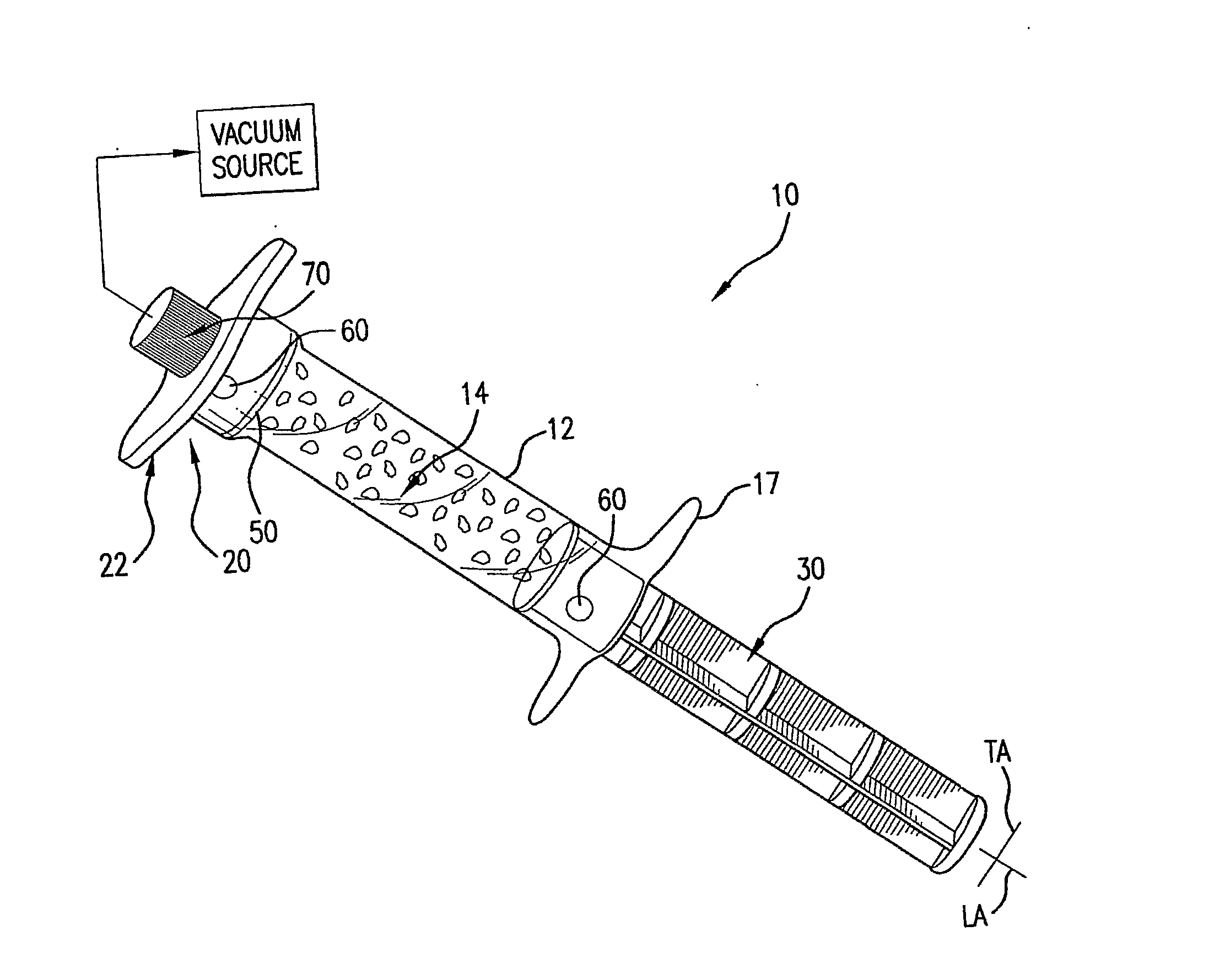
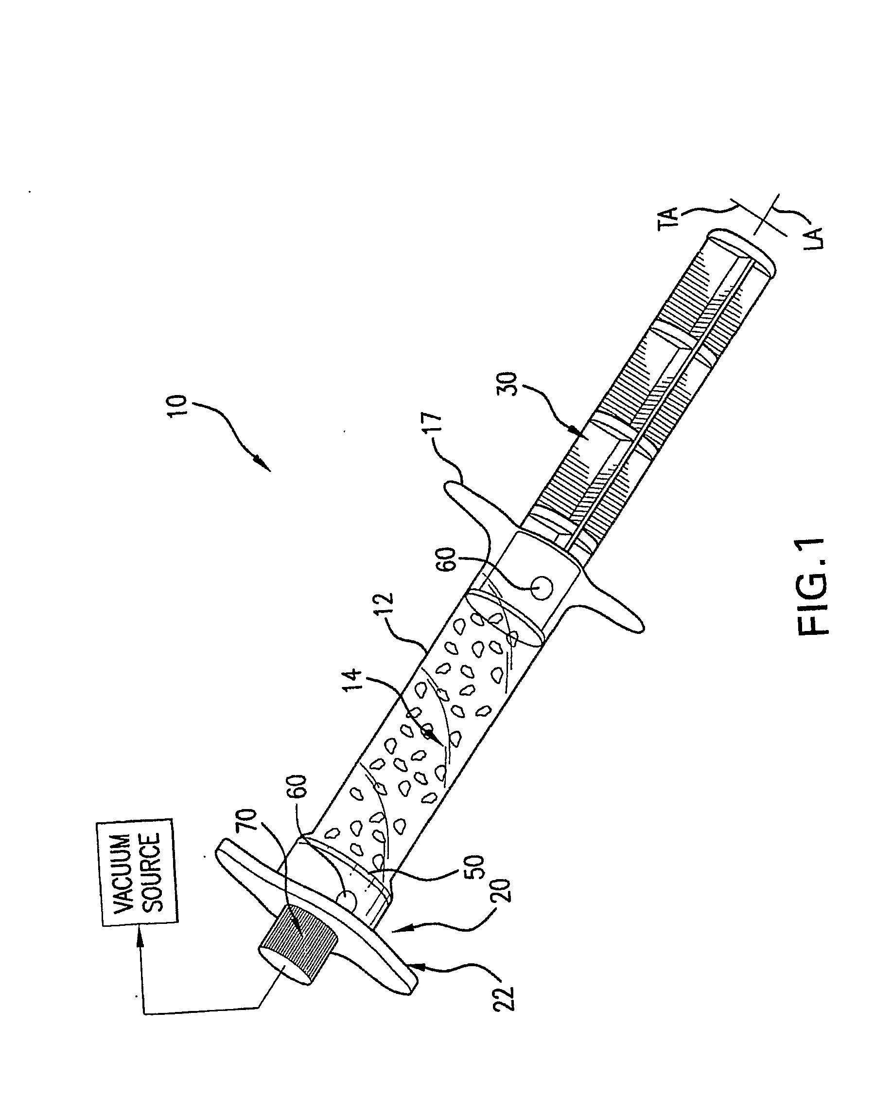
[0022]FIG. 1 is a perspective view of a preferred embodiment of a perfusion container in the form of a syringe having a biomaterial chamber;

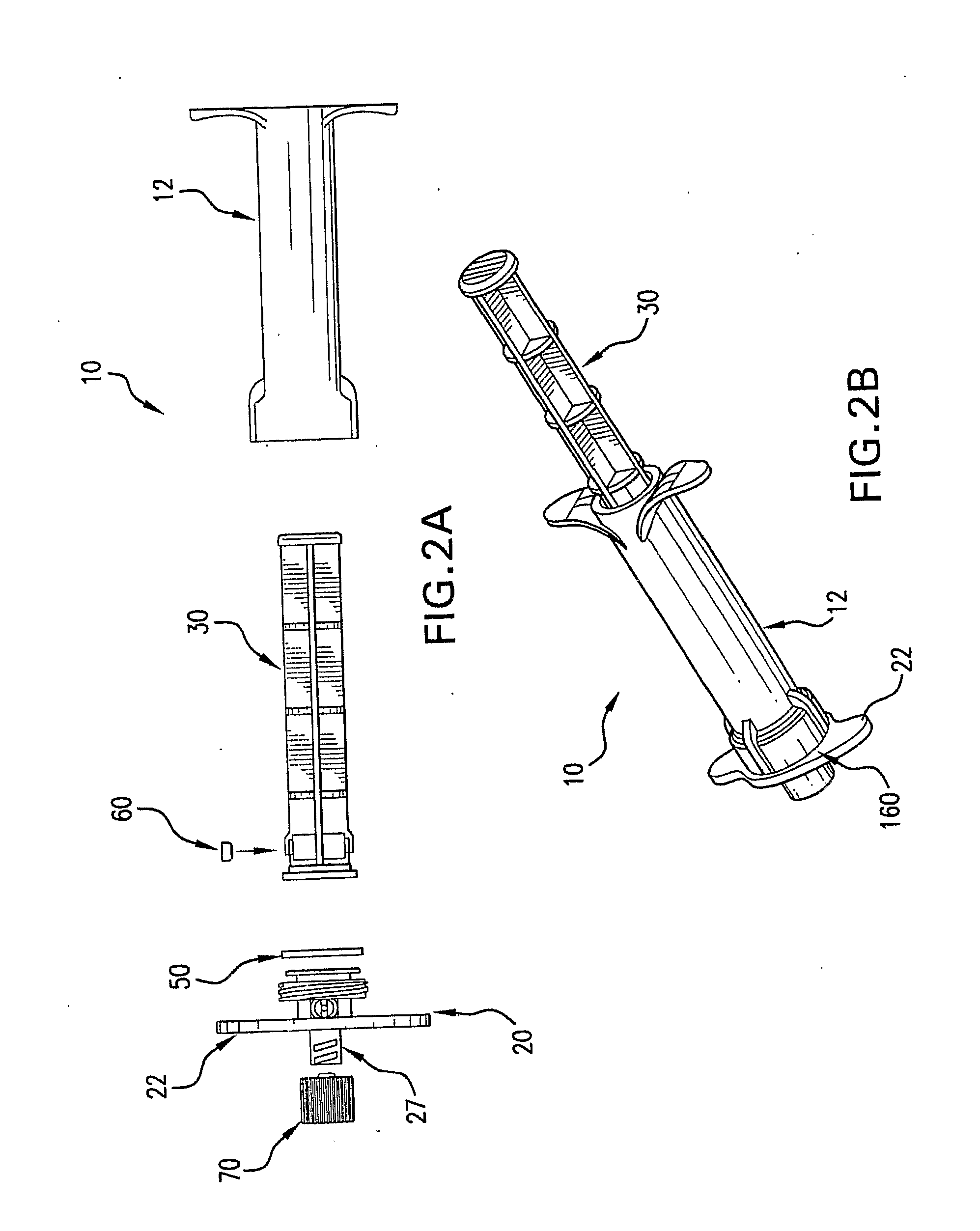
[0023]FIG. 2A shows an exploded view of the components of the perfusion syringe of FIG. 1;

[0024]FIG. 2B shows an additional perspective view of the perfusion syringe body of FIG. 1 from a different angle;

[0025]FIGS. 3A and 3B show a side view and a longitudinal cross-sectional view therethrough, respectively, of the perfusion syringe body of FIG. 1;

[0026]FIGS. 4A and 4B show a side view and a longitudinal cross-sectional view therethrough, respectively, of the perfusion syringe end cap of FIG. 1;

[0027]FIG. 4C shows an end view of the end cap of FIGS. 4A and 4B taken in the direction of line 4C-4C in FIG. 4A;

[0028]FIGS. 5A and 5B show a side view and a longitudinal cross-sectional view ...


PUM


Abstract

A perfusion device and method is provided. In one embodiment, the device includes a container having a first internal chamber configured to hold the material; a port for introducing the liquid into the chamber; a vent for releasing gas and liquid from the chamber; and a means for sealing the vent to allow a vacuum to be drawn on the first chamber The material may be biomaterial, such as a bone graft material in any form. In one embodiment, the container is a syringe that defines the internal material chamber and includes an end cap and a plunger The vent may be formed by a venting passageway in plunger and/or cap in some embodiments. In one embodiment, the vacuum may be created by a medical syringe coupled to the container, and which in some embodiments may also be used to deliver the liquid into the container The liquid may be bone marrow aspirate in some embodiments.

Description

FIELD OF THE INVENTION[0001]The present invention relates to bone repair, and more particularly to an improved device and method for perfusing an implantable bone graft biomaterial with a liquid or fluid.[0002]Gaps or voids in bone may be caused by trauma, disease, birth deformities, or other causes. In order to repair these voids, surgical procedures are used to implant biologically compatible bone graft materials into the voids. A biomaterial is broadly defined herein as any material that is compatible with in-vivo implantation. Biomaterials may include organic materials such as bone or non-organic and synthetic materials including various mineral compositions, polymers, ceramics, or other materials. The biomaterials may come in numerous forms, including pastes and cements, powders, pellets, granules, or formed geometric and other shapes. Biomaterials used in bone repair may be non-porous or porous in structure.[0003]One type of porous biomaterial that may be used for bone grafts ...

Claims


Application Information

Patent Timeline
Patent Type & Authority Applications(United States)
IPC IPC(8): A61M25/00A61B19/00A61M31/00
CPCA61B17/8827A61F2/4601A61F2/4644C12N5/0673A61F2002/2835A61F2002/30601A61F2002/4685A61F2002/2817C12N5/0669
Inventor KUREK, EDKERR, SEAN HAMILTON
Owner SYNTHES GMBH
Why Eureka
Try Eureka