Orthodontic bone screw

a bone screw and orthodontic technology, applied in the field of orthodontic treatment, can solve the problems of cumbersome multi-step surgical procedure for preparation to insert the bone screw, inability to achieve the desired fixation, and difficulty in relocating the pilot hole prior to insertion of the bone screw, etc., to achieve the effect of enhancing functional stability and cost-effectiveness

Inactive Publication Date: 2008-09-04
BALFOUR ALAN R +3
View PDF13 Cites 13 Cited by
  • Summary
  • Abstract
  • Description
  • Claims
  • Application Information

AI Technical Summary

Benefits of technology

[0005]An object of the present invention is to provide an improved intra-oral craniomaxillofacial rigid fixation screw post for primary anchorage of orthodontic appliances. Another object of the invention is the provision of an orthodontic screw that overcomes the limitations noted above of using maxillofacial reconstruction bone screws for the purpose of orthodontic post anchorage and immediate multi-axis post loading. Yet another object of the invention is the provision of an orthodontic bone screw that can easily pierce and penetrate through the soft tissue and directly into the host bone without the surgical requirements for soft tissue dissection or pre-drilling of a pilot hole. Still another object of the invention is the provision of an orthodontic screw that will enable an orthodontist to insert the screw with the sell-piercing and penetrating tip and self tapping locking threads in a single minimally invasive surgical operation. Another object of the invention is the provision of an orthodontic bone screw that once it is rigidly inserted into the host bone, standard orthodontic appliances can be attached to the exposed driving head of the screw. Another object of the invention is the provision of an orthodontic bone screw that does not permanently integrate with the host bone thereby allowing for removal at the completion of orthodontic treatment.
[0007]Briefly stated, an orthodontic, skeletal anchorage bone screw made in accordance with a preferred embodiment of the invention incorporates a sharp tissue piercing, pin-point, tack tip in series with an immediate loading, self-locking, double tapered fixation thread. Distal to the tip and body of the bone screw is a generally cylindrical, dome shaped head that incorporates features for the attachment of standard orthodontic appliances. In use, an orthodontist can easily attach the anchorage bone screw head onto a spline driver tool and insert the screw into the host bone in a single operation. Since the screw is designed for easy insertion without the requirements for soft tissue dissection or a pre-drilled pilot hole preparation, it is particularly beneficial for an orthodontist who may not be trained in dissection procedures. If desired, the screw thread, such as the uppermost portion thereof, could include suitable surface texturing to enhance functional stability. After the double, self-locking, tapered thread is rigidly fixated into the bone with the one-step surgical procedure, immediate attachment of a standard orthodontic appliance can occur. The invention allows an orthodontist to take advantage of the intra-oral anchorage post for orthodontic movement of the surrounding teeth. Further, the screw provides an orthodontist with a cost effective, complete patient compliant, functional alternative to extra oral orthodontic procedures.

Problems solved by technology

Since such screw geometries were not intended for orthodontic use, they have several limitations relative to such use.
This multiple step surgical procedure for preparation to insert the screws is not only cumbersome, but also it requires skills that are not usually performed by an orthodontist.
Since most of these surgical procedures require small diameter bone screws, relocating the pilot hole prior to insertion of the bone screw can be difficult.
Yet another limitation is that many maxillofacial reconstructive screws do not incorporate a desired fixation post head for orthodontic appliance attachment; in general these screws are used sub-gingivally and require a low profile head in order to prevent soft tissue irritation.

Method used


Image

  • Orthodontic bone screw
  • Orthodontic bone screw
  • Orthodontic bone screw

Examples


Embodiment Construction

[0016]References made in the specification and claims to a particular orientation, such as upper, bottom and the like are made with respect to the orientation as shown in the drawings.

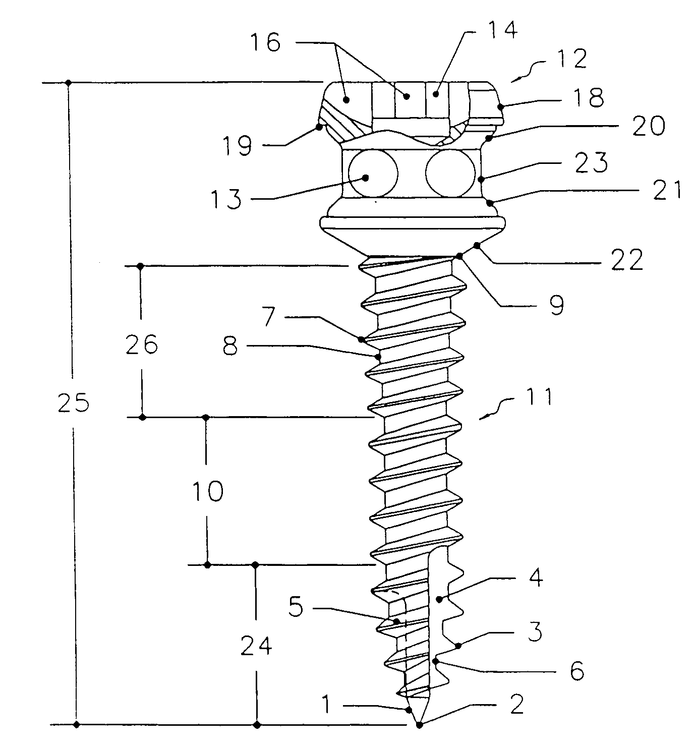
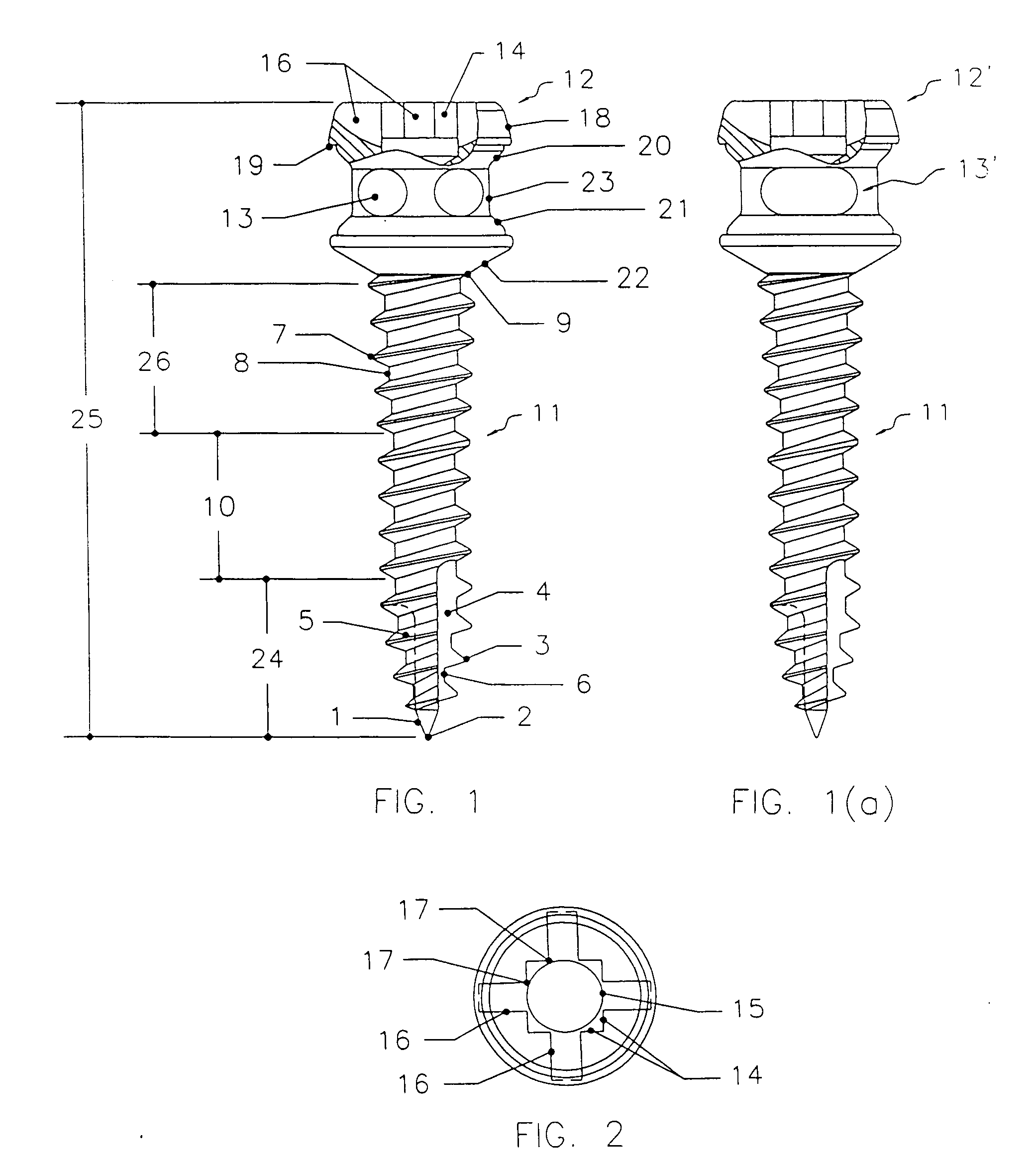
[0017]As shown in FIG. 1, the self-positioning and self-starting orthodontic bone screw of the preferred embodiment of the invention comprises an apical screw end 1 having a sharp tissue piercing pin-point tack tip 2 and an immediate loading, self-locking, double tapered threaded body 11. Distal to apical end 1 and threaded body 11 is a cylindrical, generally domed shaped driving head 12 that incorporates attachment features for orthodontic appliances. The pin-point tack tip 2 is used to locate, pierce and penetrate through the soft tissue as well as maintain a positional location in the host bone preventing the need for soft tissue dissection. Once pin-point tack tip 2 locates and tacks onto the host bone, the screw is rotated clockwise to immediately engage the apical cutting flutes 4 and 5 of the gr...


PUM


Abstract

A mechanism for separating the driver tip (28) of a driver tool (27) from an orthodontic bone screw (25) is shown. The mechanism includes a driver sleeve (36) formed with a female thread (38) that is threaded onto a male threaded portion (39) of the driver tool adjacent to the driver tip with the sleeve adapted to engage and push-off the head of the bone screw when rotated sufficiently.

Description

CROSS REFERENCE TO RELATED APPLICATIONS[0001]This is a Divisional of U.S. Ser. No. 11 / 287,673, filed Nov. 28, 2005.FIELD OF THE INVENTION[0002]This invention relates generally to orthodontic treatments and more particularly to a bone screw for use in intra-oral orthodontic corrections.BACKGROUND OF THE INVENTION[0003]Presently, a variety of bone screws are commercially available for use for orthodontic anchorage; however, many of these screws generally are intended for retaining tissue grafts and bone plates and to assist in the purpose of craniomaxillofacial reconstruction rather than for use as an orthodontic fixation post. Since such screw geometries were not intended for orthodontic use, they have several limitations relative to such use.[0004]Many bone screws that are available at the present time require one to first perform a soft tissue dissection in the area that the screw will be inserted, then to drill a pilot hole at the desired location for screw insertion. This multipl...

Claims


Application Information

Patent Timeline
Patent Type & Authority Applications(United States)
IPC IPC(8): A61B17/56A61C8/00
CPCA61C8/0022A61C8/0096A61C8/0089
Inventor BALFOUR, ALAN R.MACHATA, WILLIAM C.CARUSO, JOSEPH M.CARCHIDI, JOSEPH EDWARD
Owner BALFOUR ALAN R
Why Eureka
Try Eureka