Electrical Stimulation of Blood Vessels

a technology of electrical stimulation and blood vessels, applied in the direction of blood vessels, artificial respiration, therapy, etc., can solve the problems of blocking the lumen, achieve the effects of reducing platelet aggregation, reducing restnosis, and increasing no secretion

Active Publication Date: 2008-09-04
ENOPACE BIOMEDICAL
View PDF99 Cites 129 Cited by
  • Summary
  • Abstract
  • Description
  • Claims
  • Application Information

AI Technical Summary

Benefits of technology

[0025]For some applications, the electrode device comprises at least one stent. The electrodes are coupled to the stent, or are integrated into structural elements of the stent. For some applications, the stent comprises a bifurcation stent. The electrode device is configured to induce an increase in NO secretion by a wall of the blood vessel, typically in order to reduce platelet aggregation outside the stent (such as between the stent and the wall) and/or to minimize restenosis.
[0026]In some embodiments of the present invention, the electrode device is used to apply electrical stimulation during the process of deriving blood vessels (i.e., veins or arteries) from stem cells, such as from embryonic stem cells. Alternatively or additionally, the electrode device is used to apply electrical stimulation to blood vessels derived from stem cells after the blood vessels have been implanted in a subject. Further alternatively or additionally, the electrode device is used to apply electrical stimulation to tissue-based blood vessels created by another technique. An increase in NO production caused by such stimulation may be beneficial for the blood vessels, e.g., may aid the process of differentiating the stem cells into the blood vessels.
[0027]In some embodiments of the present invention, a counterpulsation device is adapted to be inserted in an ascending aorta and/or a descending aorta of a subject. The counterpulsation device comprises one or more electrodes, and an implantable or external control unit. The control unit is adapted to drive the electrodes to apply an electrical signal to a wall of the aorta during systole, and to configure the signal to induce an increase in NO secretion by the wall. The increased NO secretion dilates the wall such that du

Problems solved by technology

However, such growth sometimes causes platelet

Method used


Image

  • Electrical Stimulation of Blood Vessels
  • Electrical Stimulation of Blood Vessels
  • Electrical Stimulation of Blood Vessels

Examples


Embodiment Construction

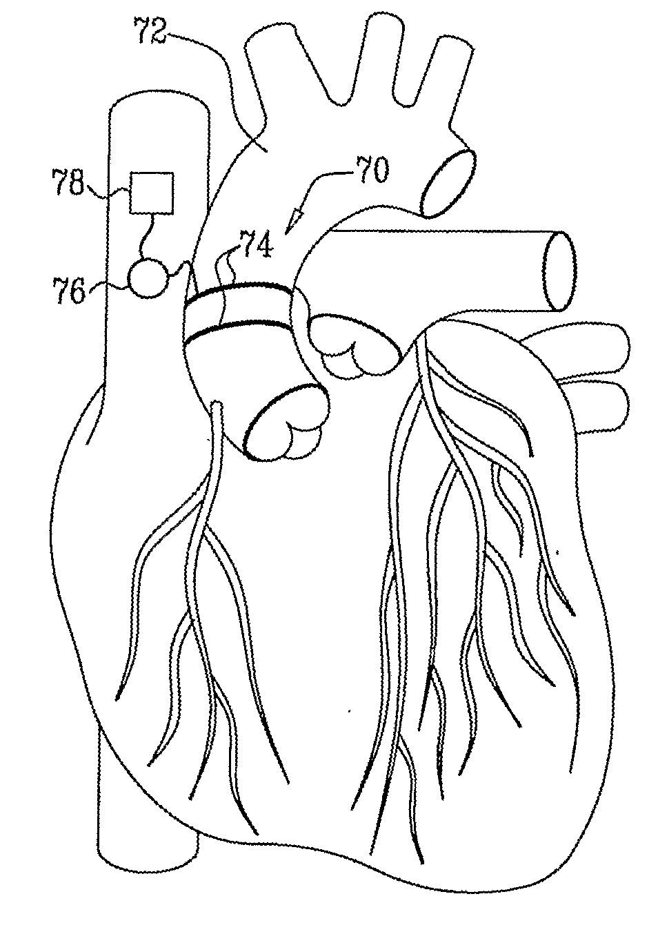
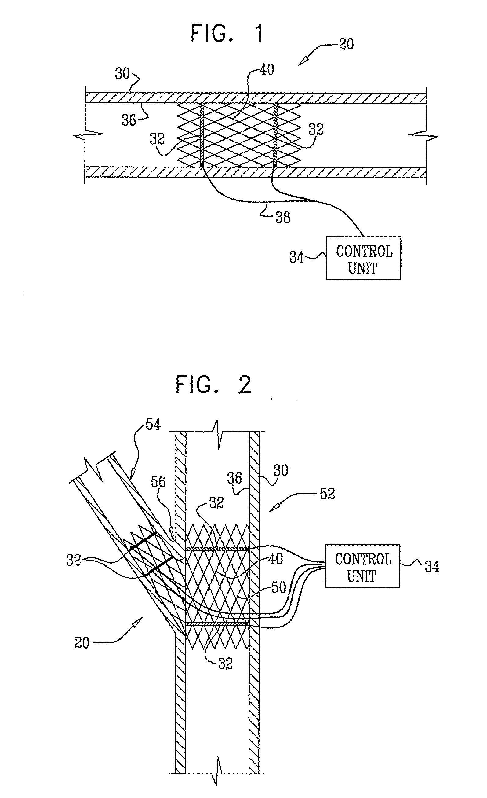
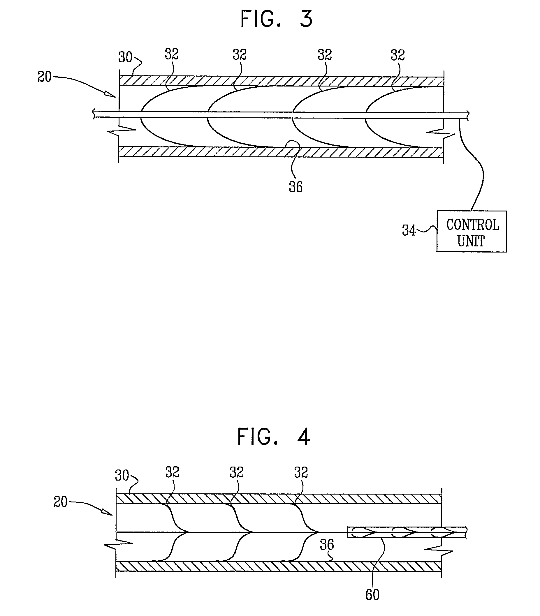
[0104]FIG. 1 is a schematic illustration of an electrode device 20 adapted to be inserted into a blood vessel 30 of a subject, in accordance with an embodiment of the present invention. Electrode device 20 comprises one or more electrodes 32, and an implantable or external control unit 34. Control unit 34 is adapted to drive electrodes 32 to apply an electrical signal to a wall 36 of blood vessel 30, and to configure the signal to induce an increase in nitric oxide (NO) secretion by wall 36. For some applications, wall 36 secretes the NO into the lumen of blood vessel 30. Alternatively or additionally, wall 36 secretes the NO into tissue of the blood vessel. For some applications, blood vessel 30 includes an atherosclerotic blood vessel. For some applications, blood vessel 30 includes a coronary artery, a bypass graft (such as a coronary artery bypass graft (CABG)), a retinal artery, a pancreatic artery, or a penile artery (e.g., to treat erectile dysfunction). The applied signal tr...


PUM


Abstract

Apparatus (20) is provided, including a bifurcation stent (50) comprising one or more electrodes (32), the stent (50) configured to be placed in a primary passage (52) and a secondary passage (54) of a blood vessel (30), and a control unit (34), configured to drive the electrodes (32) to apply a signal to a wall (36) of the blood vessel (30), and to configure the signal to increase nitric oxide (NO) secretion by the wall (36). Other embodiments are also described.

Description

CROSS-REFERENCES TO RELATED APPLICATIONS[0001]The present application claims the benefit of: (a) U.S. Provisional Application 60 / 702,491, filed Jul. 25, 2005, entitled, “Electrical stimulation of blood vessels,” and (b) U.S. Provisional Application 60 / 721,728, filed Sep. 28, 2005, entitled, “Electrical stimulation of blood vessels,” both of which applications are incorporated herein by reference.FIELD OF THE INVENTION[0002]The present invention relates generally to implantable medical devices, and specifically to methods and apparatus for stimulating and replacing blood vessels.BACKGROUND OF THE INVENTION[0003]U.S. Pat. Nos. 6,865,416 and 6,347,247 to Dev et al., which are incorporated herein by reference, describe methods for inducing or increasing the vasodilation of a vessel, or the flow of blood therethrough, including applying an electrical impulse to the vessel. According to the inventors in the '416 and 247 applications, the induction or increase of vessel vasodilation by an ...

Claims


Application Information

Patent Timeline
IPC IPC(8): A61N1/36A61F2/06A61F2/82A61M29/00
CPCA61N1/326A61F2250/0001A61F2/856A61N1/36017A61N1/05A61N1/375A61F2002/065A61F2/82A61N1/36117A61N1/056A61F2230/0008A61F2250/0004A61N1/37205A61M29/02
Inventor GROSS
Owner ENOPACE BIOMEDICAL
Why Eureka
Try Eureka