Substrate processing apparatus

Inactive Publication Date: 2008-09-11
KOKUSA ELECTRIC CO LTD
View PDF2 Cites 293 Cited by
  • Summary
  • Abstract
  • Description
  • Claims
  • Application Information

AI Technical Summary

Benefits of technology

[0016]According to one embodiment of the present invention, because, in a direction perpendicular to a supply direction of processing gas, distance between the center part of the member, is narrower than distance between a site other than the center part of the member relative to the surface to be processed of the substrate to be accommodated in the processing chamber, the processing gas supplied from the gas supply unit converges at a position corresponding to the center part of the member, and becom

Problems solved by technology

In this case, there were such cases, in some times, that film thickness decreased at the center part of the substrate, and thickness of a film formed on the substrate surface to be processed did not become uniform over the whole surface to be processed.
That is, in a substrate processing apparatus such as a CVD (chemical vapor deposition) apparatus, it is configured so that processing gas is flowed horizontally to a wafer, however, in a processing chamber of a normal-flow system, where an exhaust port is arranged at the lower end part, b

Method used


Image

  • Substrate processing apparatus
  • Substrate processing apparatus
  • Substrate processing apparatus

Examples


embodiment 1

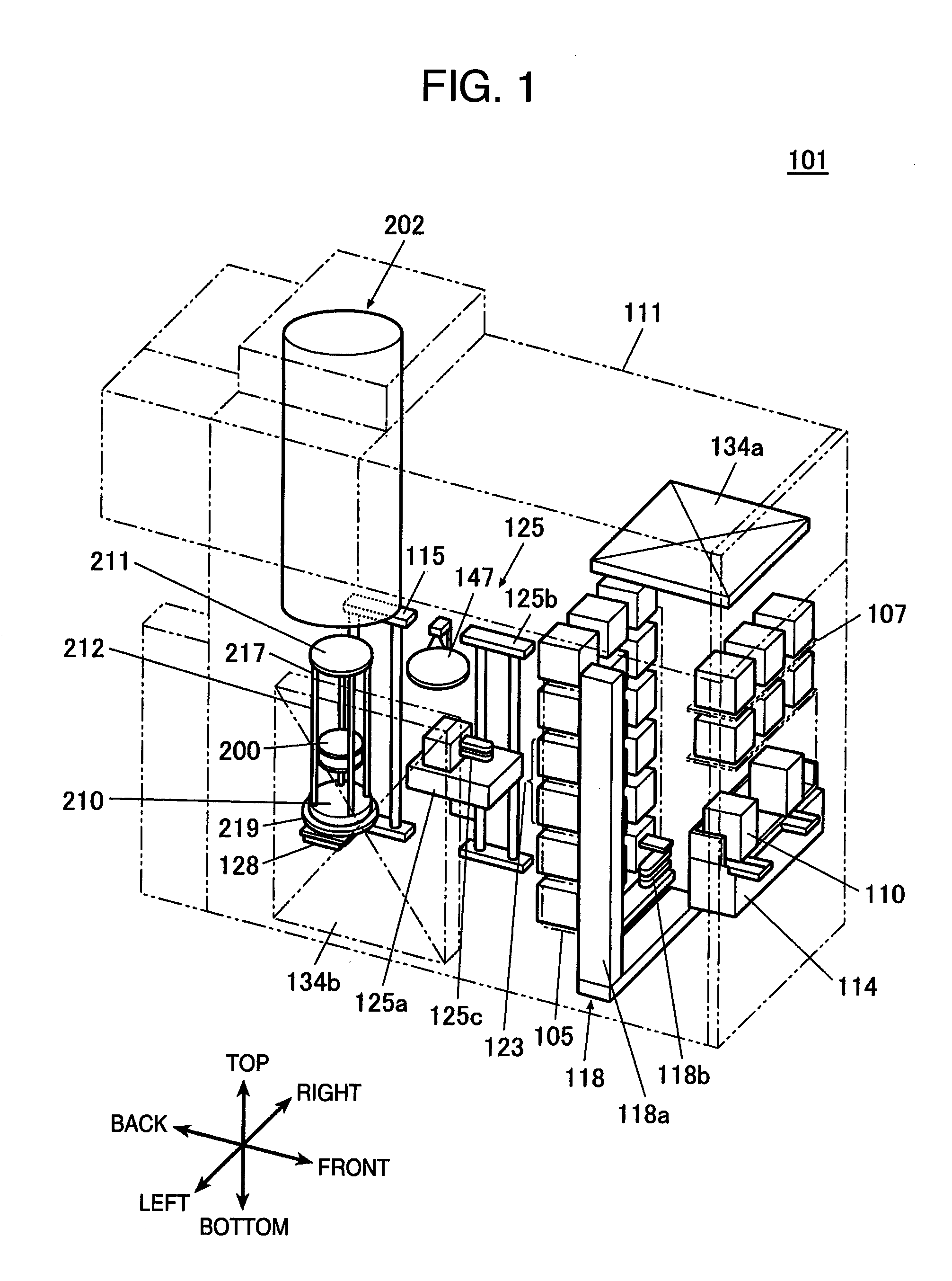
[0034]As shown in FIG. 1, in a substrate processing apparatus 101, a cassette 110 accommodating a wafer 200 of an example of a substrate is used, and the wafer 200 is configured by a material such as silicon. The substrate processing apparatus 101 is provided with a housing 111, and at the inside of the housing 111, a cassette stage 114 is installed. The cassette 110 is designed so as to be carried in onto the cassette stage 114, or carried out from the top of the cassette stage 114, by a yard carrying apparatus (not shown).

[0035]The cassette stage 114 is installed so that the wafer 200 in the cassette 110 maintains a vertical position, and a wafer gateway of the cassette 110 faces an upward direction, by the yard carrying apparatus. The cassette stage 114 is configured so as to rotate the cassette 110 clock-wise and in a longitudinal direction by 90 degree to the backward of the housing 111, and so that the wafer 200 in the cassette 110 takes horizontal position, and the wafer gate...

embodiment 2

[0116]Embodiment 2 is different mainly on the following points from Embodiment 1, and other points are nearly the same as in Embodiment 1.

[0117]In the present Embodiment 2, an adjustment plate 400 of FIG. 9 is installed, instead of the adjustment plate 300 of Embodiment 1. The adjustment plate 400 is a flat-plate-like member with equal thickness, and is configured by a dielectric substance, which is capable of consuming processing gas. The adjustment plate 400 has mainly a circumference part 410 with nearly a ring shape, and a center part 420 with nearly a circle shape, and is so configured that a linear midway part 430 is installed crossing between the circumference part 410 and the center 420.

[0118]A site between the midway parts 430 themselves, which is a site between the circumference part 410 and the center 420, is hollow (a through hole from the front surface to the back surface of the paper surface). A plurality of through holes 425 are formed at the center part 420.

[0119]In ...

embodiment 3

[0121]Embodiment 3 is different mainly on the following points from Embodiment 1, and other points are nearly the same as in Embodiment 1.

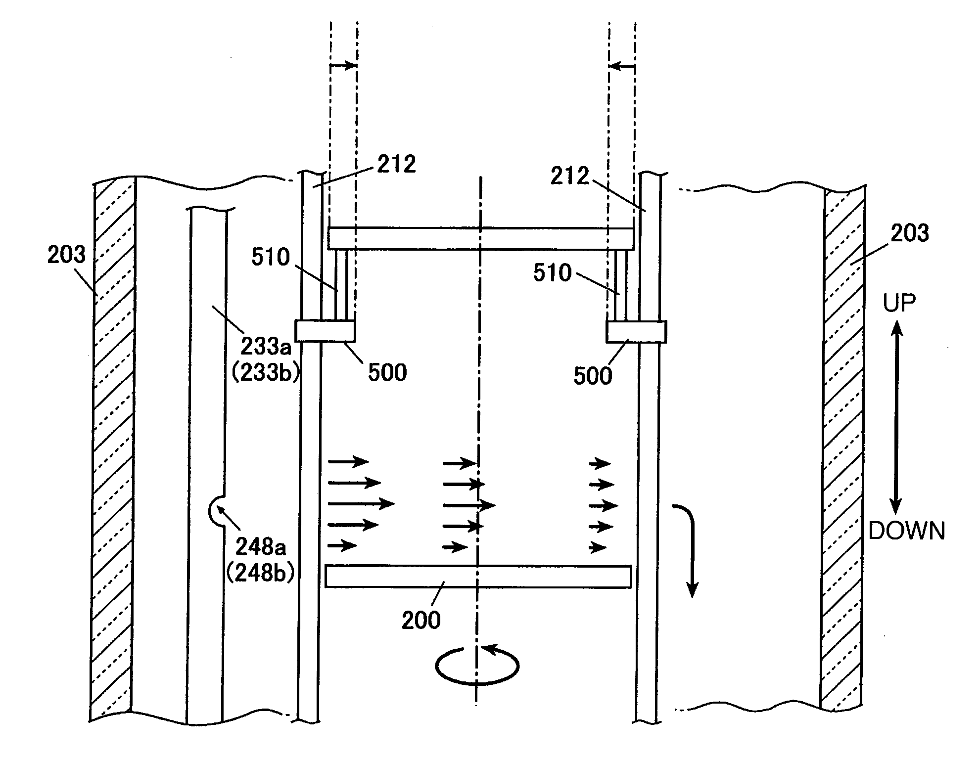
[0122]In the present Embodiment 3, a ring 500 of FIG. 10 is installed, instead of the adjustment plate 300 of Embodiment 1. The ring 500 is a ring-like member with predetermined width (from about 10 to 30 mm), and is configured by a dielectric substance, which is capable of consuming processing gas, and fixed at the support rods 212. The ring 500 is designed to be slidably and free-detachment state to the support rods 212, and still more height position thereof can be changed.

[0123]In the ring 500, a plurality of pins 510 are installed, and the wafer 200 is supported by pins 510. Inner diameter of the ring 500 is designed to be smaller than diameter (outer diameter) of the wafer 200, and a part of the ring 500 and the circumference part of the wafer 200 are overlapped in an up and down direction.

[0124]In the foregoing present Embodiment 3, process...


PUM

PropertyMeasurementUnit
Dielectric polarization enthalpyaaaaaaaaaa
Heightaaaaaaaaaa
Distanceaaaaaaaaaa

Abstract

A substrate processing apparatus having a support for holding a wafer, a processing chamber for accommodating the wafer, a gas supply hole for supplying desired processing gas in a parallel direction to the surface to be processed of the wafer to be accommodated in said processing chamber, an adjustment plate to be arranged with facing the surface to be processed of the wafer accommodated in the foregoing processing chamber, and an exhaust means for exhausting atmosphere in said processing chamber. A substrate processing apparatus wherein distance between the surface to be processed of wafer and the center part of the adjustment plate is narrower than distance between the surface to be processed of wafer and the circumference part and the midway part of the adjustment plate, in a direction perpendicular to a supply direction of processing gas.

Description

INCORPORATION BY REFERENCE[0001]The present application claims priority from Japanese application JP2007-059886 filed on Mar. 9, 2007, the content of which is hereby incorporated by reference into this application.BACKGROUND OF THE INVENTION[0002]The present invention relates to a substrate processing apparatus, in particular, relates to a substrate processing apparatus for forming a film on a substrate surface to be processed.[0003]As one example of this type of a substrate processing apparatus, there has been known an apparatus for forming a film on a surface to be processed, by accommodating a substrate in a processing chamber, and rotating the substrate thereof, and by supplying the desired processing gas toward the substrate surface to be processed. In the said apparatus, there is installed a gas supply unit for supplying desired processing gas in a direction parallel to the substrate surface to be processed, and the processing gas is designed to be supplied from the gas supply...

Claims


Application Information

Patent Timeline
IPC IPC(8): C23C16/44
CPCC23C16/45546H01L21/67309C23C16/4584C23C16/45591
Inventor TAKEBAYASHI, YUJI
Owner KOKUSA ELECTRIC CO LTD
Why Eureka
Try Eureka