Noise-comfort function for cooling systems with proportional variable speed fans

a technology of proportional variable speed and fan, which is applied in the direction of propulsion parts, electric propulsion mounting, transportation and packaging, etc., can solve the problems of undesirable noise for both passengers in the vehicle employing the cooling system and an unacceptable level of electric fan noise, and achieve the effect of reducing noise emission

Active Publication Date: 2008-09-11
GM GLOBAL TECH OPERATIONS LLC
View PDF26 Cites 25 Cited by
  • Summary
  • Abstract
  • Description
  • Claims
  • Application Information

AI Technical Summary

Benefits of technology

[0009]In concordance with the instant disclosure, a fuel cell system and method that provides a desired cooling perfo...

Problems solved by technology

Fuel cell stacks are characterized by a specific operating temperature which presents a significant design challenge, particularly with respect to a structural and an operational integrity of the fuel cell stack.
However, it is known that the electrical fans...

Method used


Image

  • Noise-comfort function for cooling systems with proportional variable speed fans
  • Noise-comfort function for cooling systems with proportional variable speed fans
  • Noise-comfort function for cooling systems with proportional variable speed fans

Examples


Embodiment Construction

[0018]The following description is merely exemplary in nature and is not intended to limit the present disclosure, application, or uses. It should also be understood that throughout the drawings, corresponding reference numerals indicate like or corresponding parts and features. In respect of the methods disclosed, the steps presented are exemplary in nature, and thus, are not necessary or critical.

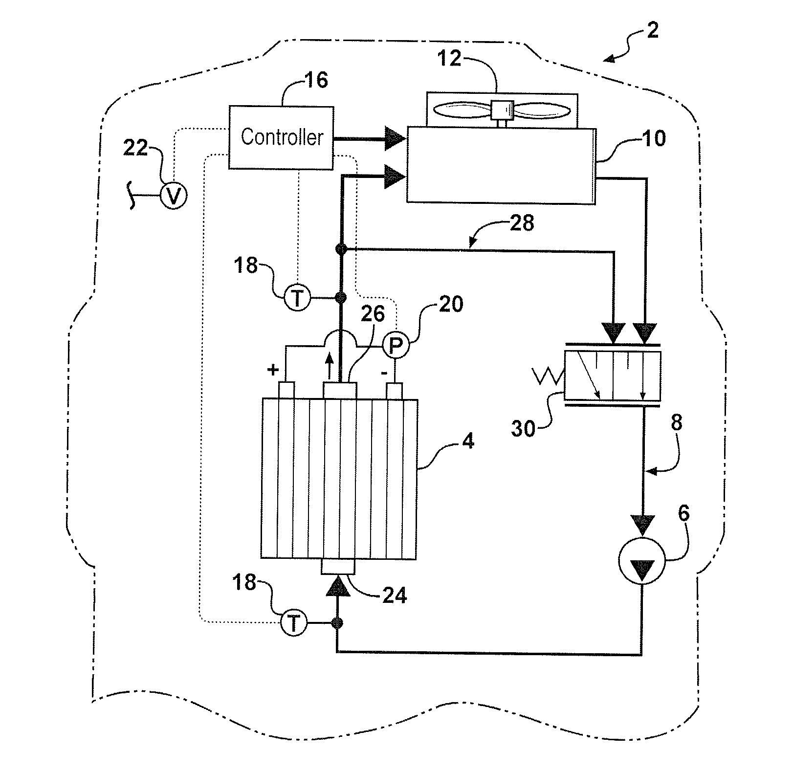
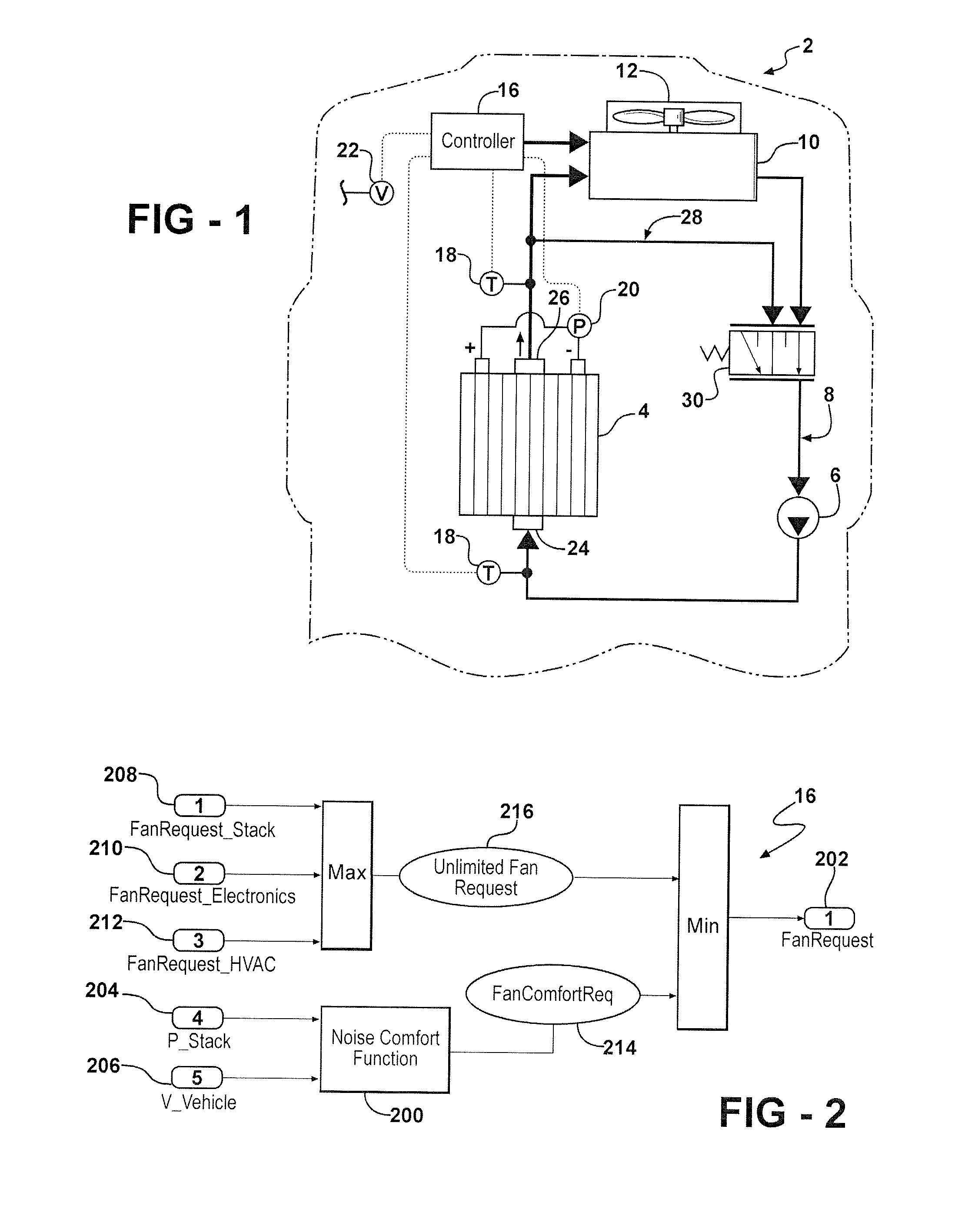
[0019]As shown in FIG. 1, the present disclosure includes a cooling system 2 for a fuel cell stack 4. In particular embodiments, the cooling system 2 is included in a vehicle (not shown) powered by the fuel cell stack 4. The cooling system 2 can include one or more pumps 6 that circulate a coolant (not shown) in a conduit 8 and through the fuel cell stack 4.

[0020]The cooling system 2 includes a chiller or coolant source 10 in fluid communication with the fuel cell stack 4. Any conventional coolant source can be used as desired. The coolant source 10 is configured to allow the coolant from...


PUM


Abstract

A method for operating a cooling system for a fuel cell stack in a vehicle is provided. The method includes the steps of: determining a fan request for a variable speed fan disposed in the cooling system; employing a noise-comfort function to select a fan comfort request; and adjusting a speed of the variable speed fan in response to the fan request; wherein a noise emission by the variable speed fan is militated against. A cooling system for a fuel cell stack in a vehicle that employs the noise-comfort function is also provided.

Description

FIELD OF THE INVENTION[0001]The present disclosure relates to fuel cell systems and more particularly to a system and method for cooling fuel cell systems.BACKGROUND OF THE INVENTION[0002]Fuel cells have been proposed as a clean, efficient and environmentally responsible power source for electric vehicles and various other applications. In particular, fuel cells have been identified as a potential alternative for the traditional internal-combustion engine used in automobiles.[0003]A fuel cell typically includes three basic components: a cathode, an anode, and an electrolyte membrane. The electrolyte membrane is sandwiched between the cathode and the anode to form a membrane-electrolyte-assembly (MEA). Hydrogen at the anode is converted to positively-charged hydrogen ions. These ions travel through the electrolyte to the cathode, where they react with oxygen. The oxygen can be supplied from air, for example. The remaining electrons in the anode flow through an external circuit to the...

Claims


Application Information

Patent Timeline
IPC IPC(8): B60K1/00B60H3/00
CPCB60K11/02Y02E60/50H01M8/04014B60K2001/005Y10S903/908
Inventor MAIER, OLIVER
Owner GM GLOBAL TECH OPERATIONS LLC
Why Eureka
Try Eureka