Low Torque Gate Valve Mechanism

a low-torque, gate valve technology, applied in the direction of valve operating means/releasing devices, mechanical equipment, transportation and packaging, etc., can solve the problems of large rim pull force, large rim diameter handwheel, and inability to achieve acceptable rim pull force levels

Inactive Publication Date: 2008-09-11
DRIL QUIP
View PDF17 Cites 16 Cited by
  • Summary
  • Abstract
  • Description
  • Claims
  • Application Information

AI Technical Summary

Benefits of technology

[0011]The present invention provides a manually operated gate valve with an operation mechanism, as well as a method for controlling fluid flow through a flowway, that reduces the torque required to actuate the gate valve and minimizes the number of handwheel turns required. In comparison to prior art gate valves, one advantage of the present invention is a lower torque requirement for opening and closing the valve. Another corresponding advantage of the present invention is that fewer turns are required to stroke the valve, which allows for faster valve actuation time assuming the handwheel is turned at a constant rate. As a consequence, the present invention minimizes the potential for gate erosion due to abrasives during transitions between open and closed positions. Yet another advantage of the present invention is the ergonomic improvement corresponding to a minimized handwheel torque and a minimized number of handwheel turns. These and other objects and advantages of the present invention will be apparent from the following.
is a lower torque requirement for opening and closing the valve. Another corresponding advantage of the present invention is that fewer turns are required to stroke the valve, which allows for faster valve actuation time assuming the handwheel is turned at a constant rate. As a consequence, the present invention minimizes the potential for gate erosion due to abrasives during transitions between open and closed positions. Yet another advantage of the present invention is the ergonomic improvement corresponding to a minimized handwheel torque and a minimized number of handwheel turns. These and other objects and advantages of the present invention will be apparent from the following.

Problems solved by technology

The handwheel may be directly threaded into the stem, but, for large or high pressure valves, such an arrangement can require impractically large amounts of rim pull force on the handwheel, or an impractically large diameter handwheel.
Valve operation mechanisms with roller screws and ball screw devices have been used to reduce torque, but such mechanisms either do not facilitate acceptable levels of rim pull force or they require an excessive number of turns to operate.
Other valve operation mechanisms have used Acme threads with bevel, spur or worm gear torque reduction boxes, but such devices have the disadvantage of requiring a high gear ratio and a correspondingly high number of turns of the handwheel.
Thus, some prior art approaches to reducing torque in manually operated gate valves have resulted in meeting desired torque levels, but such approaches nonetheless have the disadvantage of requiring an unacceptable number of handwheel turns for operation.

Method used


Image

  • Low Torque Gate Valve Mechanism
  • Low Torque Gate Valve Mechanism
  • Low Torque Gate Valve Mechanism

Examples


Embodiment Construction

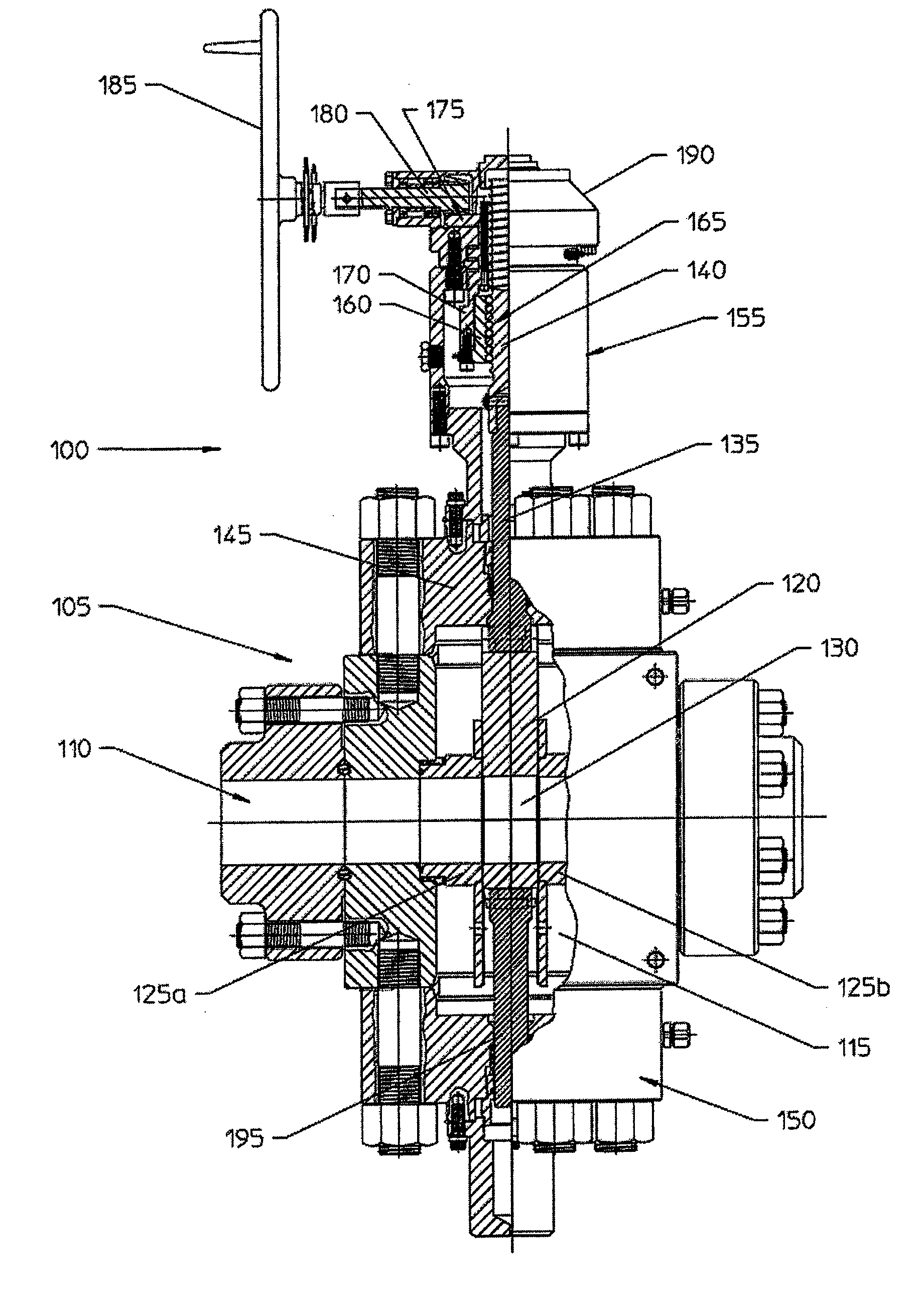
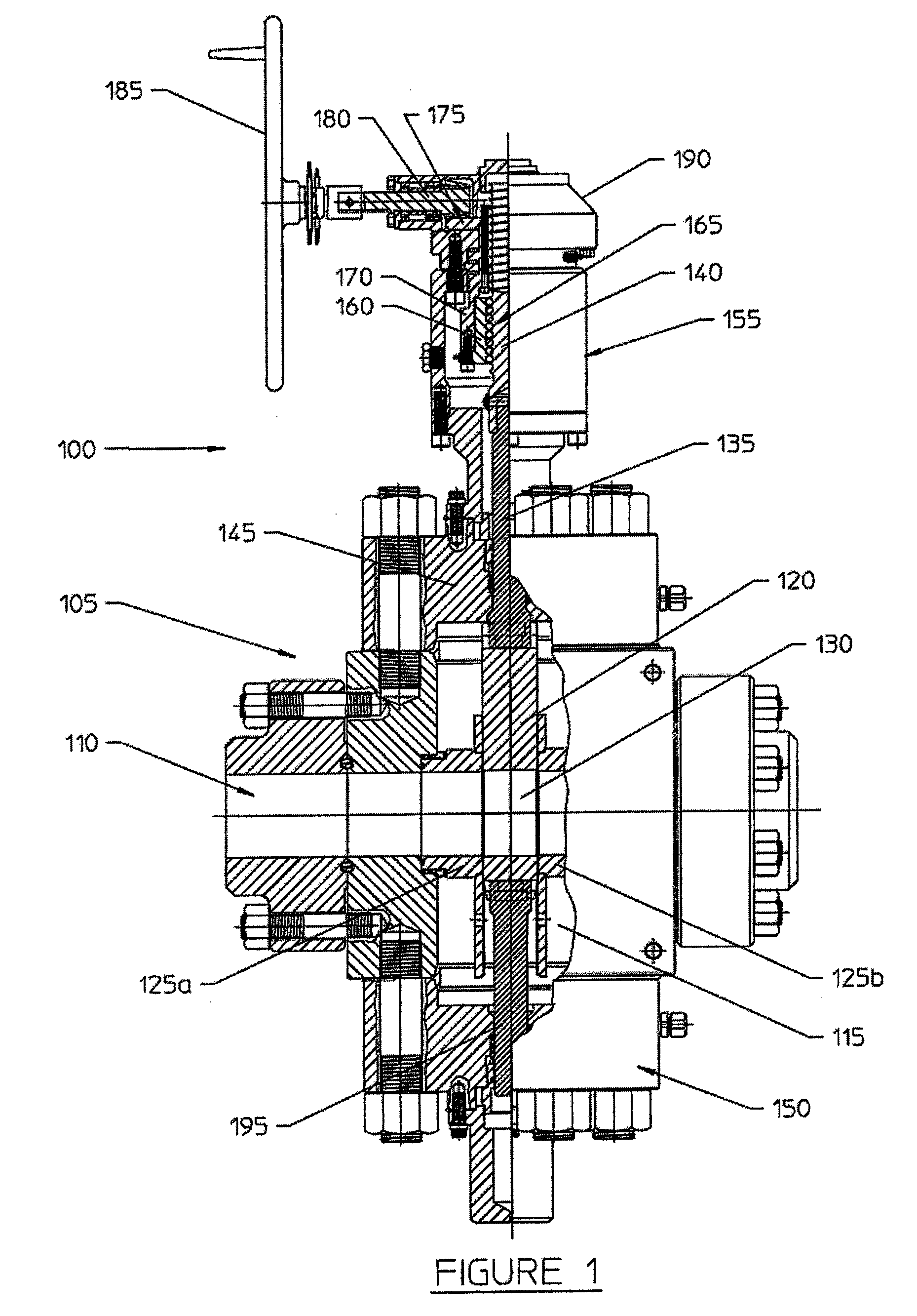
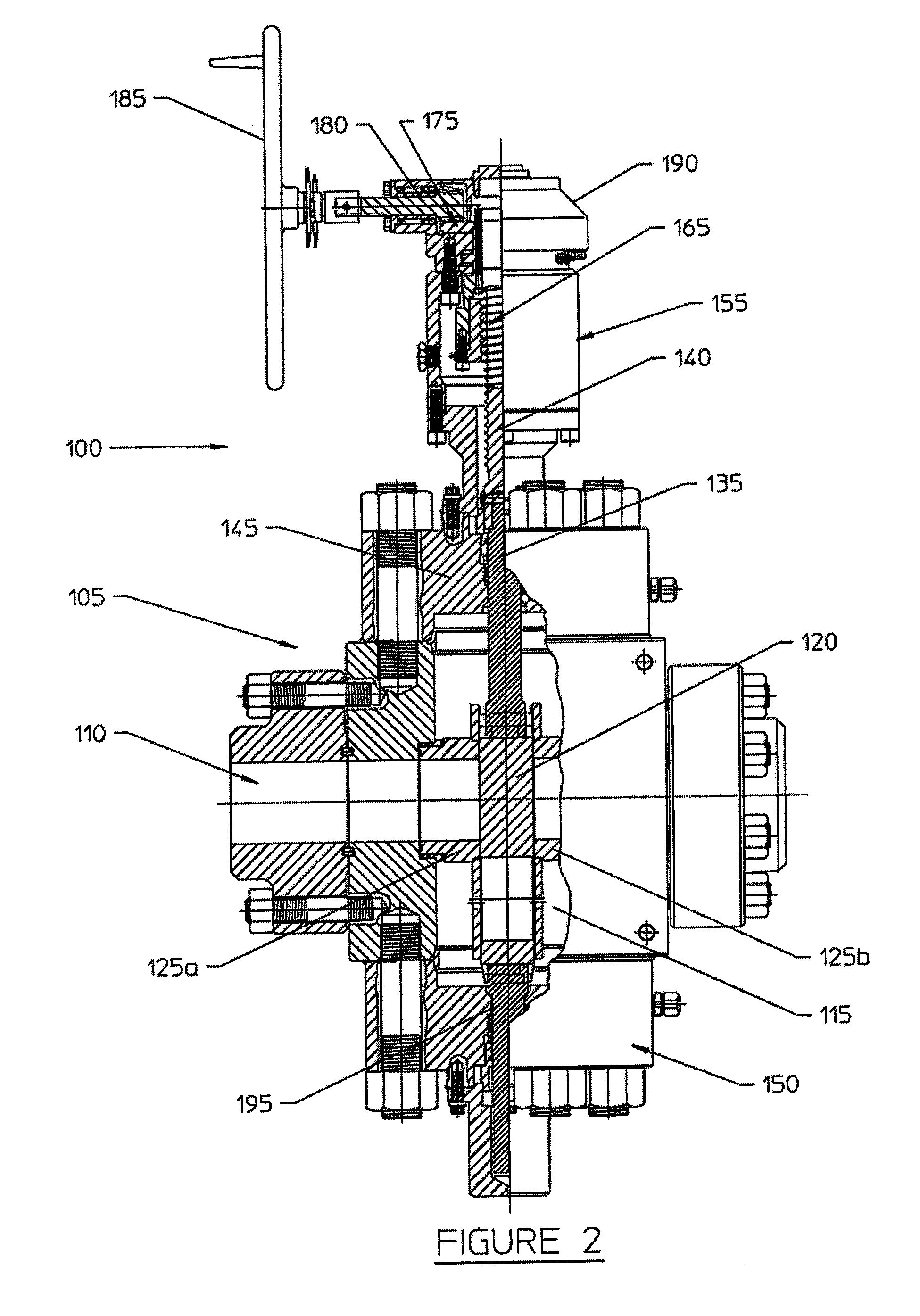
[0016]The details of the present invention will now be described with reference to the figure. Referring to FIGS. 1 and 2, shown therein is a gate valve apparatus 100, in accordance with one embodiment of the present invention. A valve body 105 includes a flowway 110 extending completely therethrough. A valve body cavity 115 extends partially through valve body 105 and intersects the flowway 110. A seat 125a and a seat 125b are sealably disposed near the intersection of the flowway 110 and the valve body cavity 115. A bonnet 145 is secured and sealed to the valve body 105 over the valve body cavity 115. An actuator housing 155 is secured to the bonnet 145, and a gear set enclosure 190 is secured to the actuator housing 155.

[0017]A gate 120 is sealably and slidably disposed between seats 125a and 125b and is suitable for reciprocal motion between at least two positions such as an open position and a closed position. When the gate valve apparatus 100 is in an open position as shown in...


PUM


Abstract

A gate valve apparatus provides a manually operated gate valve with an operation mechanism that reduces the force required to actuate the gate valve and minimizes the number of handwheel turns required. Disclosed is a gate valve apparatus including a valve body, a bonnet, a gate, a ball screw arrangement, a gear reducer arrangement and a handwheel. The ball screw arrangement, gear reducer arrangement, and the handwheel are associated with the valve stem and gate such that rotational force applied to the handwheel is converted by the gear reducer arrangement and the ball screw arrangement into linear force applied to the valve stem and then to the gate.

Description

CROSS REFERENCE TO RELATED APPLICATION[0001]This application claims the benefit of U.S. Provisional Application No. 60 / 892,942 filed on Mar. 5, 2007.BACKGROUND[0002]1. Field of the Invention[0003]The present invention is related to gate valve assemblies.[0004]2. Description of the Related Art[0005]Gate valves are commonly used in a number of industries to control the flow of fluids. Gate valves are classified as either rising stem gate valves or non-rising (or rotating) stem gate valves. A rising stem gate valve has a stem fixed to the gate such that the stem and gate move together. A non-rising stem gate valve has a stem threaded into the gate such that rotation of the stem, rather than axial movement, causes the gate to move axially.[0006]Rising stem gate valves may be further classified as either unbalanced stem gate valves or balanced stem gate valves. An unbalanced stem gate valves has a single stem associated with the gate. A balanced stem gate valve has a second stem attached...

Claims


Application Information

Patent Timeline
Patent Type & Authority Applications(United States)
IPC IPC(8): F16K3/30
CPCF16K31/50F16K3/0254Y10T137/0391F16K3/30F16K31/44
Inventor HOLLIDAY, DAVID
Owner DRIL QUIP
Why Eureka
Try Eureka