Electroacoustic Transducer
a transducer and electroacoustic technology, applied in the direction of piezoelectric/electrostrictive transducers, transducer types, generators/motors, etc., can solve the problems of difficult to reduce the thickness of piezoelectric ceramic speakers, difficult to obtain high sound pressure over a wide range of frequencies, and inability to obtain low frequency sound, etc., to achieve the effect of convenient manufacturing, high sound pressure, and inexpensive electroacoustic transducers
- Summary
- Abstract
- Description
- Claims
- Application Information
AI Technical Summary
Benefits of technology
Problems solved by technology
Method used
Image

Examples
first embodiment
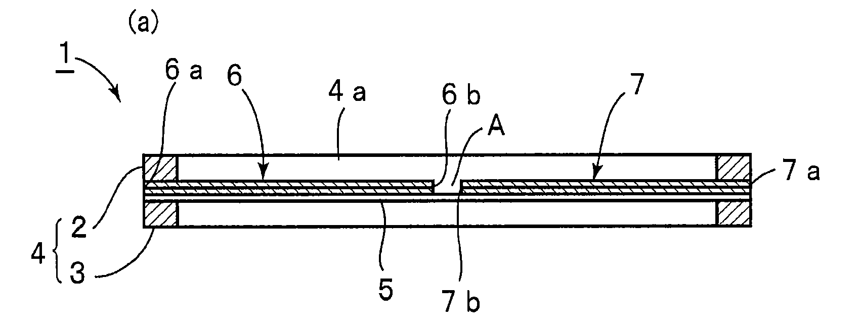
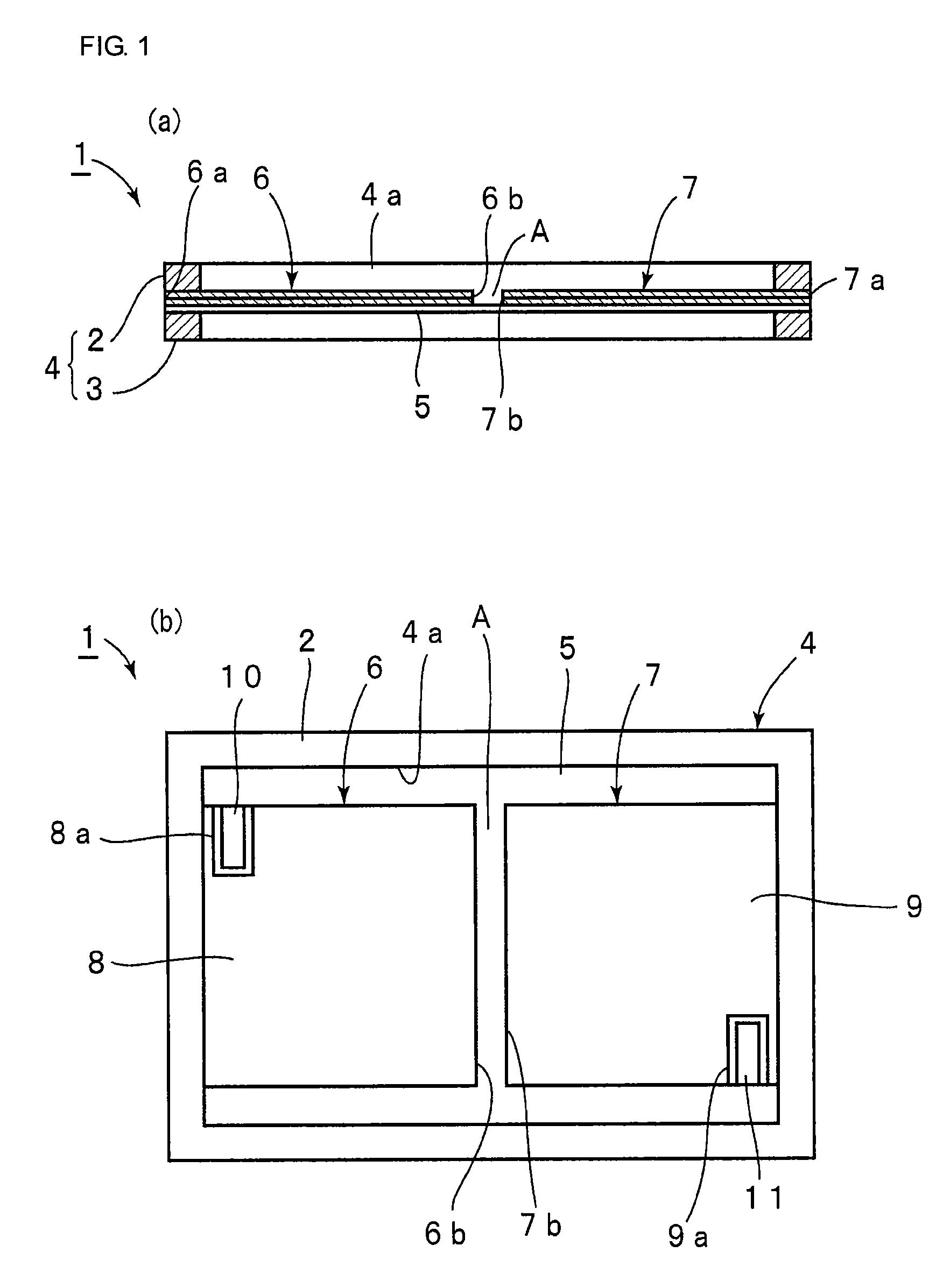
[0075]FIGS. 1(a) and 1(b) are an elevational cross-sectional view and a plan view of an electroacoustic transducer according to the present invention, respectively. An electroacoustic transducer 1 is suitable for use as a piezoelectric speaker. The electroacoustic transducer 1 includes a frame 4 obtained by bonding a first frame member 2 and a second frame member 3 together. The frame members 2 and 3 are made of an appropriate rigid material such as metal or ceramic. In this embodiment, the frame members 2 and 3 are made of metal.
[0076]The frame 4 includes an opening 4a. In the opening 4a, a flexible thin film 5 is bonded to the frame 4 so that it covers the entire area of the opening 4a. More specifically, the peripheral portion of the flexible thin film 5 is sandwiched and fixed between the frame members 2 and 3 so that the flexible thin film 5 covers the entire area of the opening 4a.
[0077]The flexible thin film 5 is composed of a flexible thin film made of a material that is no...
second embodiment
[0092]FIG. 3 is a plan view of an electroacoustic transducer according to the present invention. In an electroacoustic transducer 21, the piezoelectric elements 6 and 7 face each other with a gap therebetween in the opening 4a of the frame 4. At the gap A, a rigid plate 22 having a rigidity higher than that of the flexible thin film 5 is bonded to the flexible thin film 5. The rigid plate 22 can be made of an appropriate material having rigidity higher than that of the flexible thin film 5. In this embodiment, the rigid plate 22 is composed of a fiber reinforced plastic plate having a thickness that is substantially the same as that of the piezoelectric elements 6 and 7. The thickness of the rigid plate 22 is not necessarily substantially the same as that of the piezoelectric elements 6 and 7. It is desirable that the rigid plate 22 be made of the lightest material with high rigidity.
[0093]The rigid plate 22 is bonded to the flexible thin film 5. Accordingly, when the piezoelectric ...
third embodiment
[0094]FIG. 4 is a plan view of an electroacoustic transducer according to the present invention. In an electroacoustic transducer 31, first to fourth piezoelectric elements 32 to 35 are provided in the opening 4a of the frame 4. More than two piezoelectric elements may be provided in the opening 4a.
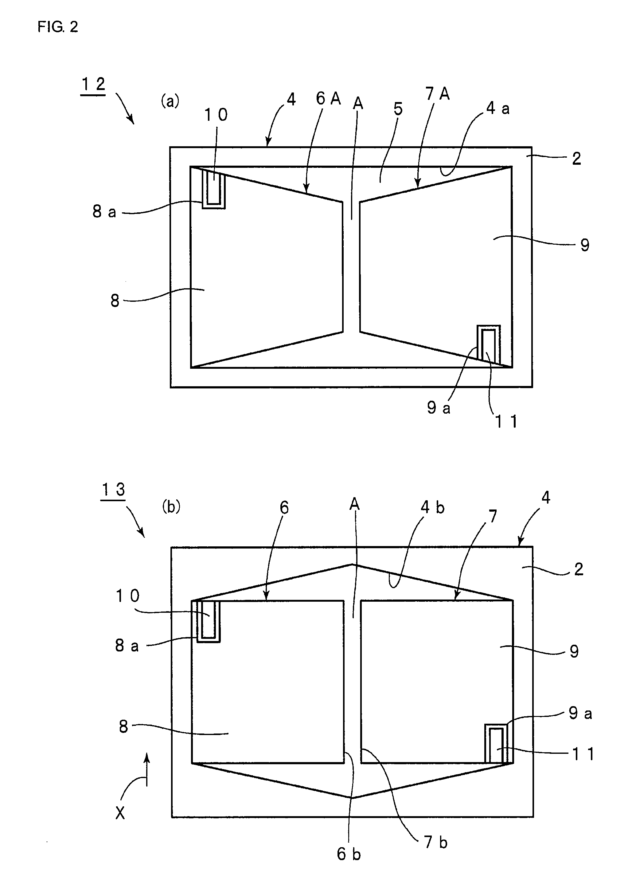
[0095]Like the piezoelectric elements 6A and 7A used in the electroacoustic transducer 12, the piezoelectric elements 32 to 35 each has a substantially trapezoidal shape. Each of the piezoelectric elements 32 to 35 has an upper base at a tip portion thereof, and is fixed to the frame 4 at a lower base thereof. In this embodiment, the flexible thin film 5 is similarly fixed to the frame 4 so that it covers the entire area of the opening 4a. In a gap region A on the side of the tip portion of each of the piezoelectric elements 32 to 35 having a substantially trapezoidal shape, a rectangular rigid plate 30 is bonded to the flexible thin film 5. Accordingly, in this embodiment, using the rig...
PUM
 Abstract
Description
Claims
Application Information
 - R&D
- Intellectual Property
- Life Sciences
- Materials
- Tech Scout
- Unparalleled Data Quality
- Higher Quality Content
- 60% Fewer Hallucinations
Browse by: Latest US Patents, China's latest patents, Technical Efficacy Thesaurus, Application Domain, Technology Topic, Popular Technical Reports.
© 2025 PatSnap. All rights reserved.Legal|Privacy policy|Modern Slavery Act Transparency Statement|Sitemap|About US| Contact US: help@patsnap.com