Coil of a force-measuring system, and method of manufacturing the coil

a force-measuring system and coil technology, applied in the direction of transformers/inductance coils/windings/connections, magnets, magnet bodies, etc., can solve the problems of weight change, drift of the zero point of the measuring scale, and change of compensation force, so as to achieve precise control of shape

Inactive Publication Date: 2008-09-11
METTLER TOLEDO AG
View PDF13 Cites 23 Cited by
  • Summary
  • Abstract
  • Description
  • Claims
  • Application Information

AI Technical Summary

Benefits of technology

[0032]This solution has the advantage that due to the approximately rectangular cross-sectional wire profile a high fill ratio can be achieved. Since the windings in an upper layer can be arranged largely unaffected by the winding arrangement of the layer below it, there will be no irregularities except for those of negligible importance in the end zones of a coil. Even with the multiple crossovers of the kind that have a particularly strong effect in multifilar and specifically in bifilar wiring arrangements, the available space is being used effectively and the fill ratio is thus increased.
[0052]It is further possible that the manufacturing process includes a step in which the coil wires are joined together into a wire combination and wound onto a drum. The axis of the drum is preferably oriented parallel to the axis of the windings of the coil that is to be produced. This prevents the preassembled wire combination from becoming twisted in the intermediate storing phase.

Problems solved by technology

This causes on the one hand a weight change of the coil over time and thus a drift of the zero point of the measuring scale.
On the other hand, the humidity favors the occurrence of leakage currents, which leads to changes of the compensation force.

Method used


Image

  • Coil of a force-measuring system, and method of manufacturing the coil
  • Coil of a force-measuring system, and method of manufacturing the coil
  • Coil of a force-measuring system, and method of manufacturing the coil

Examples


Embodiment Construction

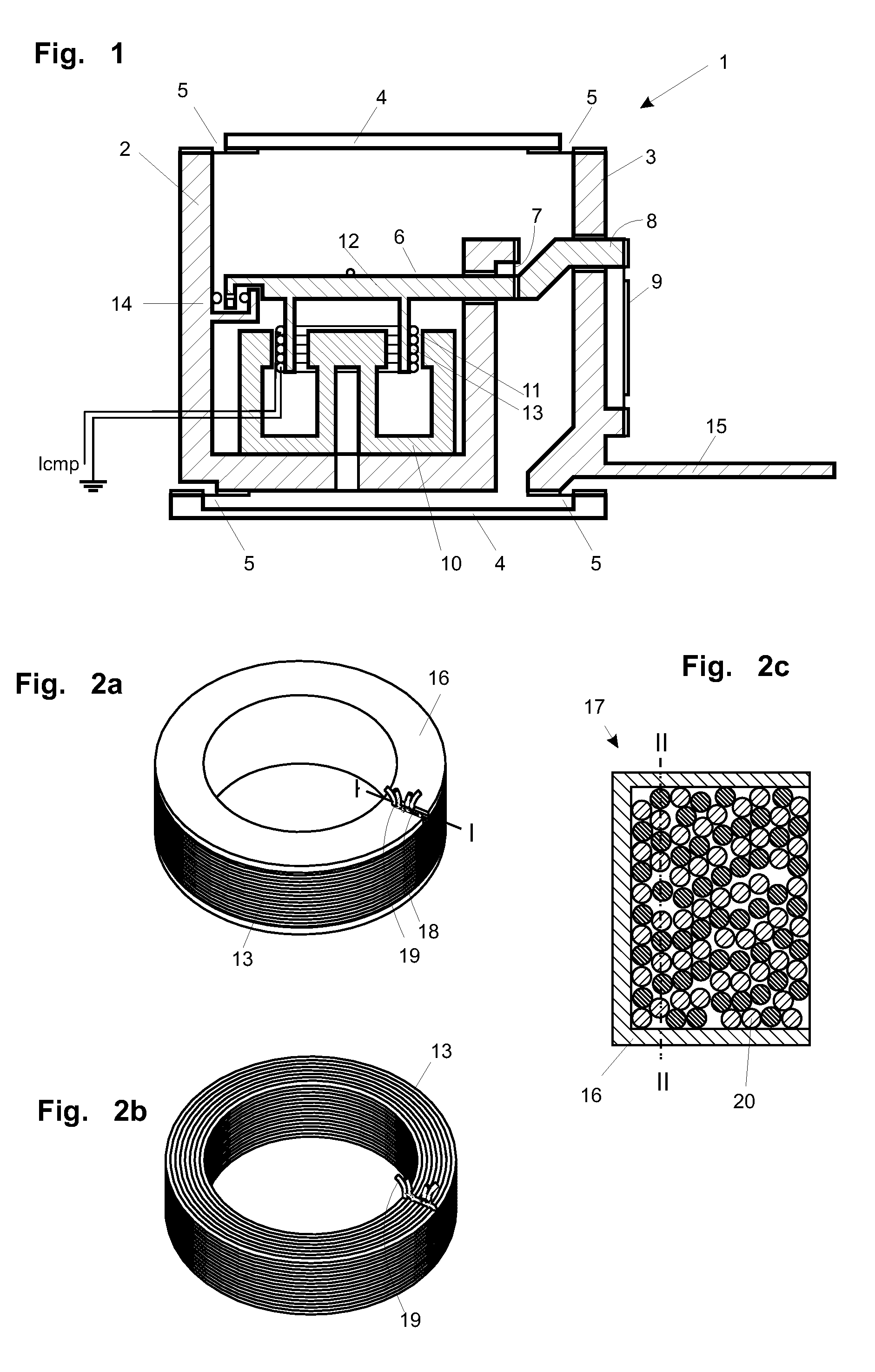
[0062]FIG. 1 represents a strongly simplified schematic view of a force-measuring cell 1 which is based on the principle of electromagnetic force compensation and is suitable for use in the field of weighing technology. The force-measuring cell 1 includes a force-transmitting device with a parallel-guiding mechanism that has a stationary part 2 and a vertically movable part 3 which are pivotably connected to each other through flexure pivots 5 at the ends of a pair of guide members 4. The vertically movable part 3 has a cantilevered portion 15 serving to receive a load that is to be measured. The normal component of the force generated by a load is transmitted from the vertically movable part 3 through a coupling element 9 to the short lever arm 8 of the lever 6. The lever 6 is supported on a portion of the stationary part 2 by means of a flexure fulcrum 7. The force-measuring cell further includes a cup-shaped permanent magnet system 10 which is arranged in fixed connection with th...


PUM

PropertyMeasurementUnit
lengthsaaaaaaaaaa
pressureaaaaaaaaaa
forceaaaaaaaaaa

Abstract

A multi-layered electromagnetic coil for a force-measuring system is based upon the principle of electromagnetic force compensation, as is a method for manufacturing the coil. The coil has a multifilar, specifically bifilar, wiring arrangement of coil wires. Preferably, the coil wires have a substantially rectangular cross-sectional profile. The cross-sectional profile of the coil wire is designed for achieving the densest possible packing of the windings in the coil can be achieved.

Description

CROSS-REFERENCE TO RELATED APPLICATIONS[0001]This application claims a right of priority under 35 USC §119 from European patent application 07103513.3, filed 5 Mar. 2007, the content of which is incorporated by reference as if fully recited herein.TECHNICAL FIELD[0002]The present invention relates to a multi-layered electromagnetic coil for a force-measuring system based on the principle of electromagnetic force compensation, and to a method of manufacturing the coil.BACKGROUND OF THE ART[0003]The electromagnetic coil is suitable for a force-measuring system of the type described in commonly-owned U.S. Pat. No. 6,326,562 B1, to Burkhard, et al, which is based on the principle of electromagnetic force compensation and finds application for example in the field of weighing technology.[0004]This force-measuring device contains a force-transmitting device which includes a parallel-guiding mechanism and often a lever mechanism for the reduction of a force that is to be transmitted, for e...

Claims


Application Information

Patent Timeline
Patent Type & Authority Applications(United States)
IPC IPC(8): H01F27/28H01F7/06
CPCH01F27/2823Y10T29/49071G01G7/02H01F41/0691H01F41/077
Inventor BALTISBERGER, STEPHANMETZGER, ANDREASKOEPPEL, THOMAS
Owner METTLER TOLEDO AG
Why Eureka
Try Eureka