
Image processing apparatus, image forming apparatus, image processing method, and computer readable recording medium

Active Publication Date: 2008-09-11
SHARP KK
View PDF9 Cites 18 Cited by
  • Summary
  • Abstract
  • Description
  • Claims
  • Application Information

AI Technical Summary

Benefits of technology

[0011]An object of the invention is to provide an image processing apparatus, an image forming apparatus, an image processing method, and a computer readable recording medium, each capable of improving the image quality of the image obtained by the tone reproduction processing, and further of allowing the scale of the apparatus to be reduced.

Problems solved by technology

Since a fixed error diffusion coefficient is applied to all of the pixels in the error diffusion method, an accumulative error becomes periodical, resulting in textures or worms.
Therefore, it requires only smaller size of hardware than that of the error diffusion method for performing the pseudo tone reproduction process.
In the case in which all of the pixels are processed with the blue noise mask method, there arises a problem that the peripheries of characters and line drawings become awkwardly spattering in the output, or that an awkward granular output is caused in a halftone dot area by interference with the original halftone pattern, although different form the moire occurred in the dither method, unless the halftone dot area is sufficiently smoothed in the former process.
Thus, there arises a problem that in the error diffusion method which requires an already large-scale apparatus, growth in size of the processing circuit occurs, or a large capacity line buffer for storing the quantization error or the accumulated error becomes necessary.

Method used


Image

  • Image processing apparatus, image forming apparatus, image processing method, and computer readable recording medium
  • Image processing apparatus, image forming apparatus, image processing method, and computer readable recording medium
  • Image processing apparatus, image forming apparatus, image processing method, and computer readable recording medium

Examples


first embodiment

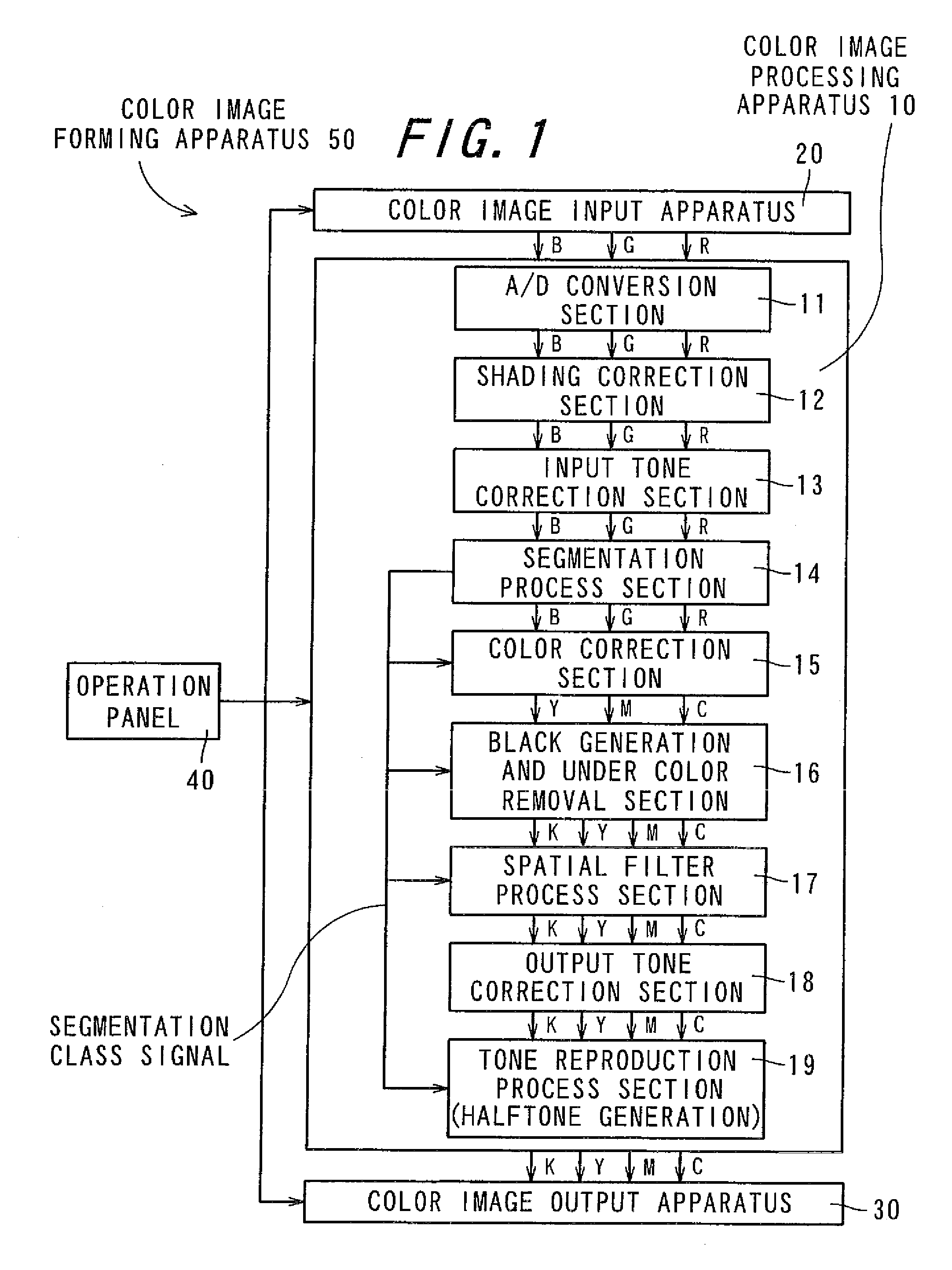
[0094]FIG. 1 is a block diagram showing a schematic configuration of a color image forming apparatus 50 according to a first embodiment of the invention. The color image forming apparatus 50 comprises a color image processing apparatus 10, a color image input apparatus 20, a color image output apparatus 30, and an operation panel 40, and can be realized as, for example, a color digital color copier.

[0095]As shown in FIG. 1, the color image processing apparatus 10 comprises an analog / digital (A / D) conversion section 11, a shading correction section 12, an input tone correction section 13, a segmentation process section 14, a color correction section 15, a black generation and under color removal section 16, a spatial filter process section 17, an output tone correction section 18, and a tone reproduction process section 19.

[0096]The color image input apparatus 20 is constituted by a scanner section provided, for example, with a charge coupled device (hereinafter referred to as CCD) i...

second embodiment

[0130]In a second embodiment of the invention, the configuration of the tone reproduction process section 19 is simplified compared to one in the first embodiment of the invention, and configurations of other sections than the tone reproduction process section 19 are the same as in the first embodiment of the invention, and description thereof will be, therefore, omitted.

[0131]FIG. 8 is a block diagram showing a configuration of the tone reproduction section 19 according to the second embodiment of the invention. The tone reproduction process section 19 comprises an adder 191a, a quantization process section 194, a quantization threshold value storage section 195, a quantization error calculation section 191d, a diffusion error calculation section 191e, an error diffusion coefficient storage section 191f realized with a ROM and so on, and an accumulated error storage section 191g.

[0132]The configuration of the tone reproduction section 19 in the present embodiment is similar to the...

third embodiment

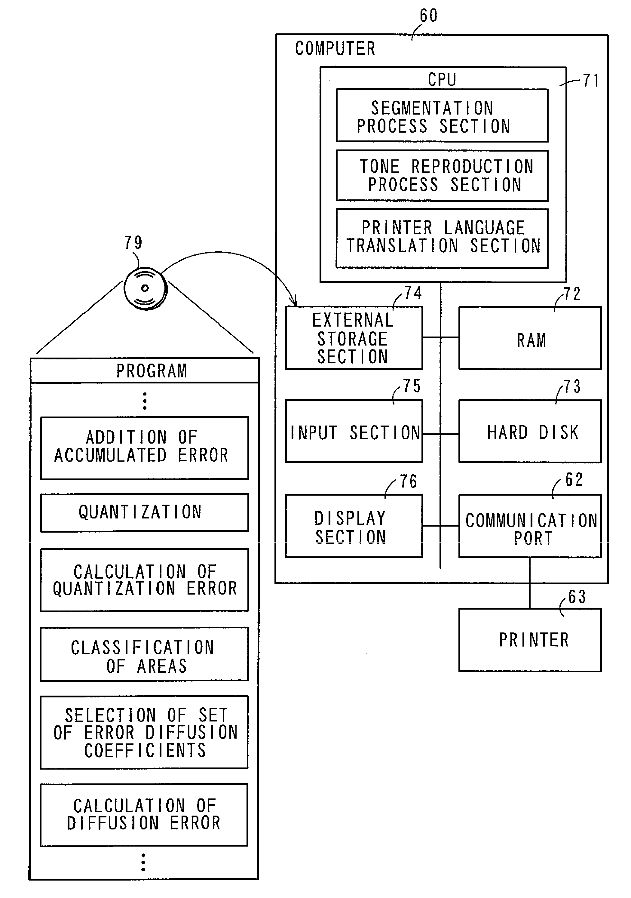
[0136]FIG. 9 is a diagram showing a configuration of a computer 60 according to a third embodiment of the invention. The computer 60 is configured including the segmentation process section 14, the tone reproduction process section 19, a printer language translation section 61, and a communication port 62, and is connected to a printer 63 as the image output apparatus 63. The same configurations as in the embodiments described above are denoted by the same reference numerals, and description thereof will be omitted.

[0137]The printer 63 can be a digital multi-function peripheral having a copy function and a facsimile function in addition to the printer function. Further, the printer 63 performs an electrophotographic image formation or an inkjet image formation.

[0138]The image data is inputted to the computer 60 from an image scanner such as a flatbed scanner or a film scanner, or a digital camera, for example, and stored in a storage device such as a hard disk drive (not shown).

[013...


PUM


Abstract

An error diffusion process section performs an error diffusion process on a pixel value of each of processing object pixels and outputs the processed pixel value to an output selection section. A blue noise mask process performs a blue noise mask process on a pixel value of each of processing object pixels and outputs the processed pixel value to the output selection section. The output selection section selects and outputs the pixel value outputted from the error diffusion process section when a segmentation class signal indicates a character (text) area or a halftone dot area, namely an edge area, and selects and outputs the pixel value outputted from the blue noise mask process section when a segmentation class signal indicates an area other than the character area or the halftone dot area, namely non-edge area.

Description

CROSS-REFERENCE TO RELATED APPLICATION[0001]This application claims priority to Japanese Patent Application No. 2007-060944, which was filed on Mar. 9, 2007, the contents of which are incorporated herein by reference in its entirety.BACKGROUND OF THE INVENTION[0002]1. Field of the Invention[0003]The present invention relates to an image processing apparatus, an image forming apparatus, an image processing method, and a computer readable recording medium, each capable of converting image data inputted thereto into image data with a predetermined gray level level.[0004]2. Description of the Related Art[0005]In recent years, digitalization of office automation (OA) equipment has rapidly progressed, and a demand for color image output has increased, which has caused image output apparatuses such as an electrophotographic digital color copier or an inkjet or thermal transfer color printer to be in widespread use. For example, image data inputted from an image input apparatus such as a di...

Claims


Application Information

Patent Timeline
IPC IPC(8): H04N1/40
CPCH04N1/4051H04N1/4092H04N1/4052
Inventor MURAKAMI, YOSHINORI
Owner SHARP KK
Learn More