
Horizontal Meat Slicer with Bandsaw Blade

a bandsaw blade and horizontal cutting technology, applied in bandsaws, metal sawing devices, manufacturing tools, etc., can solve the problems of most dangerous devices, large loss to meat packing companies, and high cost of meat products, so as to eliminate the concern of meat products accidentally twisting or rotating, and improve the quality of the cut.

Inactive Publication Date: 2008-09-18
BIGGS HENRY +1
View PDF7 Cites 10 Cited by
  • Summary
  • Abstract
  • Description
  • Claims
  • Application Information

AI Technical Summary

Benefits of technology

The present invention is a horizontal meat slicer that includes a frame and two conveyor belts. The lower conveyor belt receives and transfers the meat product through the device, while the upper pressing conveyor belt compresses the meat product between it and the lower conveyor belt. A rotating blade mounted on the frame cuts the meat product as it passes through the device. The use of both bandsaw-type blades and circular butterfly slicing blades allows for various types of cutting. The invention improves the quality of the cut and reduces the risk of the meat product becoming twisted or rotated during the cutting process.

Problems solved by technology

The cutting and processing of meat products can be a very hazardous occupation due to the various blades and saws which must be used.
Each year, thousands of man-hours are lost to injuries sustained by meat packing plant workers, which causes great loss to the meat packing company, let alone the physical damage the employee suffers.
Two of the most dangerous devices are the bandsaw meat cutter and the butterfly slicing machine, due to the need for an operator of the machine to manually feed the meat product being cut into the device to contact the cutting blade.
Obviously, if the operator is pressing the meat product into contact with the rapidly rotating blade, one slip is all that is needed to result in extremities being severed from or horrific cuts being made to the operator's body.
Various devices have been proposed in the prior art to feed the meat product into contact with the cutting blades, but each of these includes at least one inherent shortcoming which does not fully address the problem presented.

Method used


Image

  • Horizontal Meat Slicer with Bandsaw Blade
  • Horizontal Meat Slicer with Bandsaw Blade
  • Horizontal Meat Slicer with Bandsaw Blade

Examples


Embodiment Construction

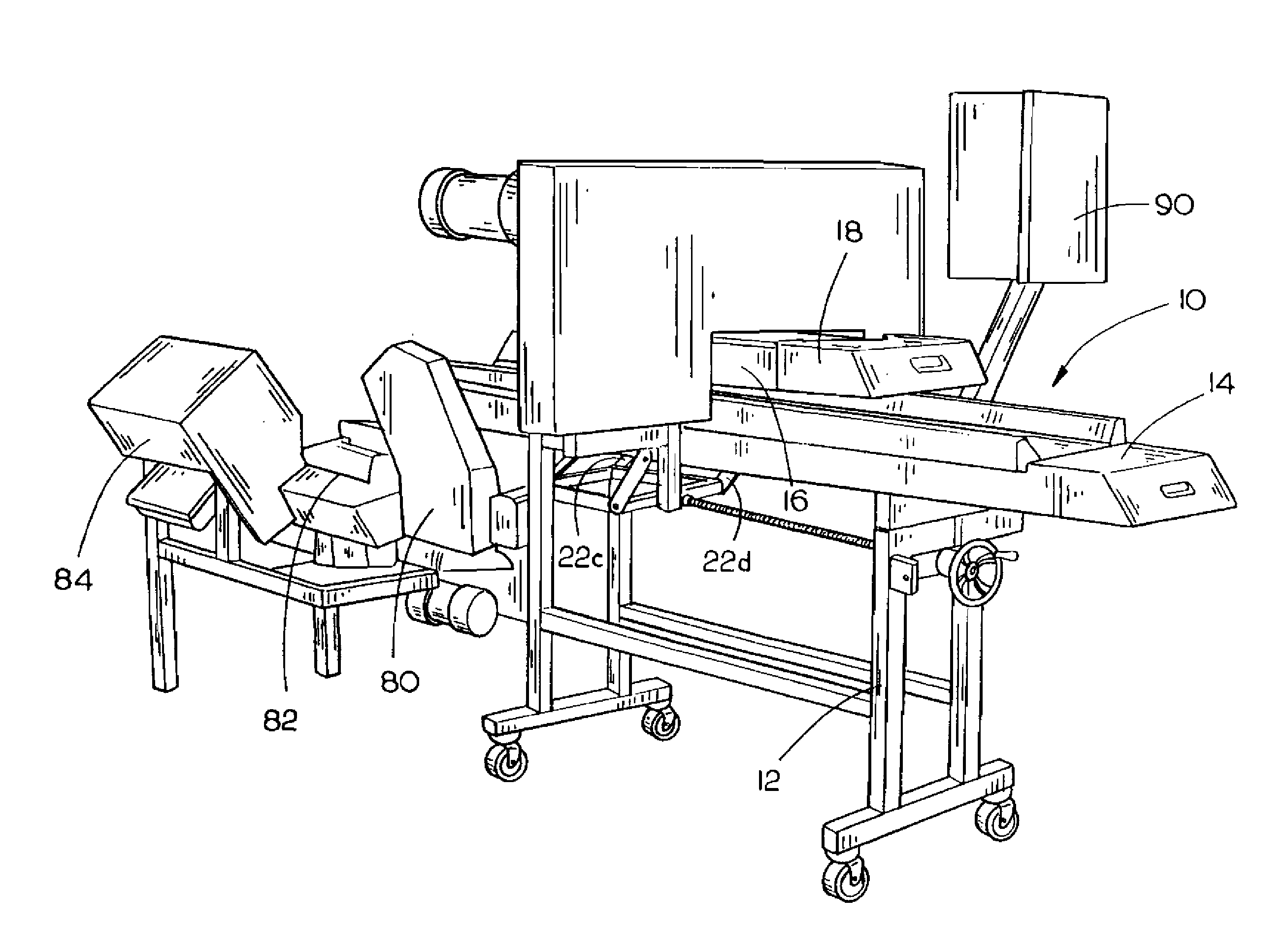
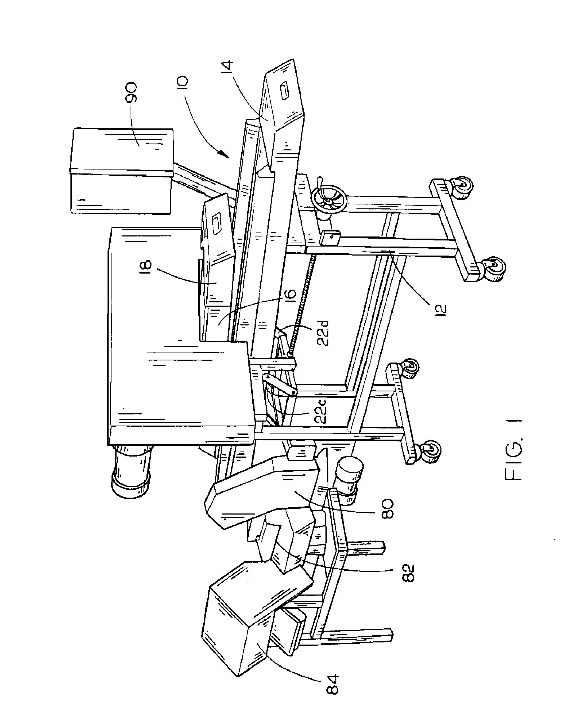
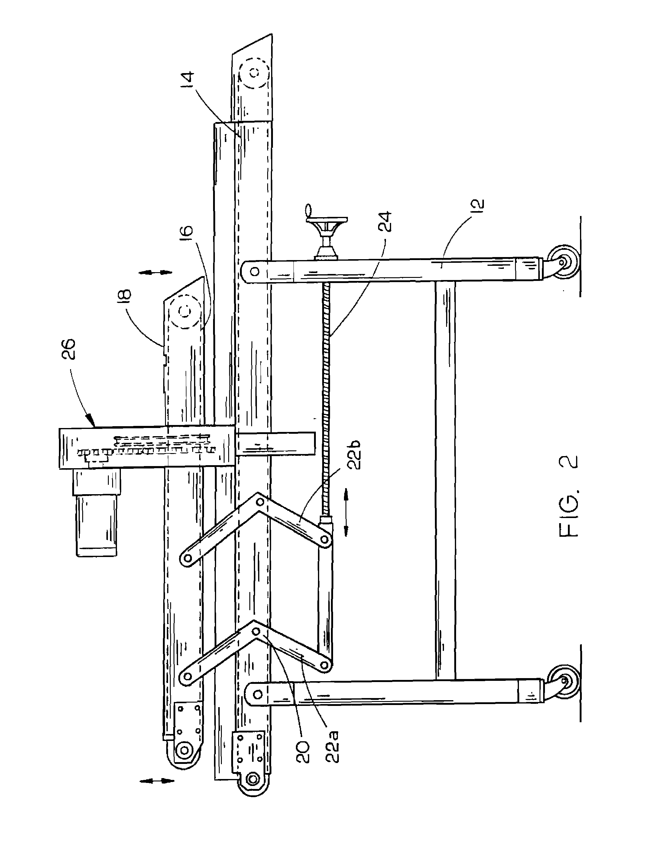
[0024]The horizontal meat slicer 10 of the present invention is shown best in FIGS. 1-5 as including a frame 12 on top of which is mounted a generally horizontal lower conveyor belt 14. As shown in FIGS. 1 and 2, belt 14 would preferably have a length of approximate seven to nine (7 to 9) feet, a width of approximately 12 to 18 inches and be constructed of a flexible rubber compound which is simple to clean and is durable in construction. Movably mounted above lower conveyor belt 14 and extending generally parallel therewith is an upper pressing conveyor belt 16 which extends parallel with and is adjustably spaced from lower conveyor belt 14. The upper pressing conveyor belt 16 is preferably mounted underneath a housing 18 which prevents accidental touching of the upper conveyor belt 16, thus preventing injury. Upper conveyor belt 16 and lower conveyor belt 14 cooperate to “sandwich” meat product placed therebetween and secure the meat product from movement during the slicing proces...


PUM

PropertyMeasurementUnit
widthaaaaaaaaaa
widthaaaaaaaaaa
heightaaaaaaaaaa

Abstract

A horizontal meat slicer includes a frame and a lower conveyor belt having forward and rearward ends, the lower conveyor belt operative to receive a meat product thereon and transport it into and through the device. An upper pressing conveyor belt includes forward and rearward ends, the upper pressing conveyor belt and the lower conveyor belt cooperating such that meat product is compressed between the lower conveyor belt and the upper pressing conveyor belt. At least one bandsaw blade is rotatably mounted on the frame, a cutting section of the bandsaw blade traveling between the upper belt and lower belts. Finally, at least one drive device such as a motor is operatively connected to each of the conveyor belts and the bandsaw blade to drive them to pull the meat product through the device and cut the meat product via the cutting edge of the bandsaw blade.

Description

CROSS-REFERENCE TO RELATED APPLICATION[0001]This continuation application claims priority to the filing date of related patent application Ser. No. 11 / 051,570 filed on Feb. 4, 2005, in turn related to patent application Ser. No. 10 / 339,867 filed on Jan. 11, 2003, in turn to related patent application Ser. No. 09 / 699,713 filed on Oct. 30, 2000 and to related provisional application Ser. No. 60 / 162,039 filed Oct. 28, 1999.BACKGROUND OF THE INVENTION[0002]1. Field of the Invention[0003]The present invention relates to meat slicing machines and, more particularly, to a horizontal meat slicing machine which includes upper and lower conveyor belt mechanisms which cooperate to transport meat product through the machine, at least one generally horizontal slicing blade interposed between the upper and lower conveyor belts for slicing meat product transported therethrough and height adjustment mechanisms for the blade and upper conveyor belt which will permit various types of cuts to be made ...

Claims


Application Information

Patent Timeline
Patent Type & Authority Applications(United States)
IPC IPC(8): A47J43/00B26D1/46B26D1/48B26D7/06A22B5/20A22C17/00B23D53/02B23D55/04B26D1/147B26D1/50B26D3/08B26D7/02
CPCA22C17/0013B23D53/026B23D55/046B26D1/147B26D7/0625B26D1/50B26D3/08B26D7/02B26D1/46Y10T83/6579Y10T83/707Y10T83/7189Y10T83/7226
Inventor BIGGS, HENRYKORTELEY, STEVE
Owner BIGGS HENRY
Learn More