Liquid cooling system of an electric machine

a technology of liquid cooling system and electric machine, which is applied in the direction of lighting and heating apparatus, magnetic circuit rotating parts, magnetic circuit shape/form/construction, etc., can solve the problems of limiting the performance of electric machines, reducing the efficiency of electric machines, and increasing the heat produced by electric machines

Active Publication Date: 2008-09-18
BORGWARNER INC
View PDF10 Cites 83 Cited by
  • Summary
  • Abstract
  • Description
  • Claims
  • Application Information

AI Technical Summary

Benefits of technology

[0007]The present invention solves the aforementioned problems by providing a liquid cooling system for an electric machine including a frame heat conductively attachable to a stator of an electric machine. The liquid cooling system further includes a cover mechanically attached to the frame and fluidly sealed to the frame, the cover and frame defining a cavity therebetween. The cover includes at least one protrusion extending substantially a distance between the cover and the frame.

Problems solved by technology

As higher voltage and higher power electric machines are utilized in vehicles and the like, a problem regarding the fact that such electric machines produce an increasing amount of heat is realized.
The constraints of casting design and fabrication result in a cooling jacket of substantial thickness.
Since the overall package size of the electric machine is usually restricted by available space in, for example, a vehicle, the cast cooling jacket thickness is disadvantageous because it limits a space available for the electric machine stator and thereby limits the performance of the electric machine.
The brazed joints, however, have low mechanical strength and are vulnerable to cracking under vibration, which will result in a fluid leak and potential failure of the electric machine.
The brazed cooling jackets are less efficient at heat transfer because the interior of the jackets have a decreased surface area simply due to a smaller diametrical dimension of the outer surface of the cooling jacket as compared to that dimension of the cast jacket, which as noted must be thicker.
Additionally, because the interior walls of the brazed cooling jackets are smooth compared to the cast cooling jacket, the result is a less turbulent flow of the cooling fluid through the jacket, and consequently less effective cooling.

Method used


Image

  • Liquid cooling system of an electric machine
  • Liquid cooling system of an electric machine
  • Liquid cooling system of an electric machine

Examples


Embodiment Construction

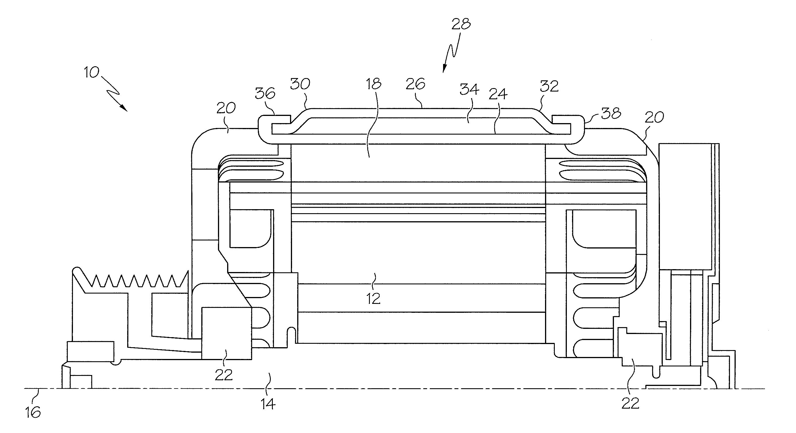
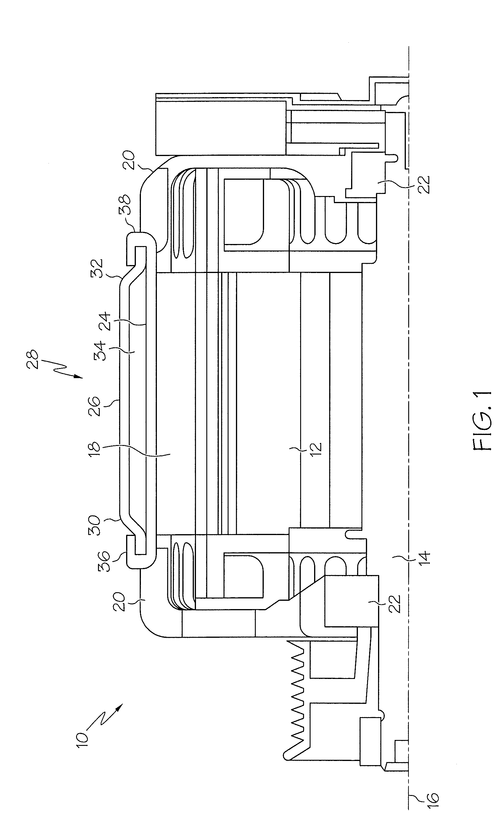
[0020]Shown in FIG. 1 is a fluid-cooled electric machine 10. The type of electric machine shown in FIG. 1 is a belt-driven alternator starter (BAS), but applications of this invention to other electric machines such as generators and / or alternators is contemplated. Electric machine 10 includes a rotor 12 disposed circumferentially about a shaft 14, and rotable with the shaft 14 about a rotor axis 16. Extending axially along the rotor axis 16 and surrounding the rotor 12 is a stator 18. The stator 18 comprises a plurality of conductive windings (not shown) disposed on a stator core (not shown). Enclosing the electric machine 10 at each axial end is an end bell 20, the shaft 14 extending through a bell hole 22 therein.

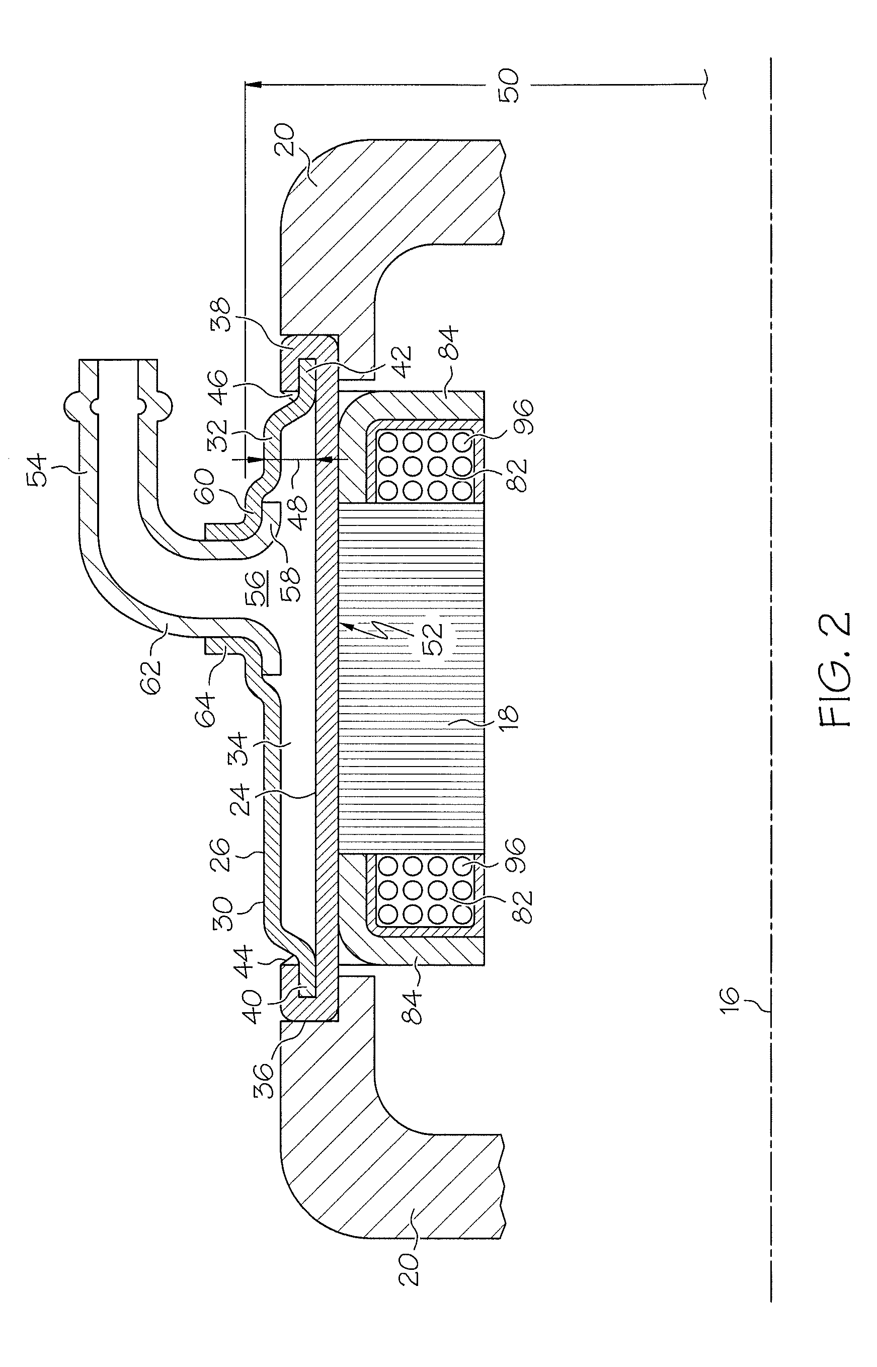
[0021]A frame 24 is placed entirely around an outer surface of the stator 18 to maximize thermal contact between the frame 24 and the stator 18. In one embodiment, this is accomplished by shrink-fitting the frame 24 to the stator 18, but other means are contemplated with...


PUM

PropertyMeasurementUnit
thicknessaaaaaaaaaa
diameteraaaaaaaaaa
diameteraaaaaaaaaa

Abstract

Disclosed is a liquid cooling system for an electric machine including a frame heat conductively attachable to a stator of an electric machine. The liquid cooling system further includes a cover mechanically attached to the frame and fluidly sealed to the frame, the cover and frame defining a cavity therebetween. The cover includes at least one protrusion extending substantially a distance between the cover and the frame. A method for constructing a liquid is also provided. The method includes forming at least one protrusion in the cover and structurally affixing the cover to the frame. The cover is fluidly sealed to the frame.

Description

CROSS REFERENCE TO RELATED APPLICATION[0001]This application is a non-provisional application of U.S. Ser. No. 60 / 895,241, filed Mar. 16, 2007, the contents of which are incorporated by reference herein in their entirety.BACKGROUND OF THE INVENTION[0002]The present invention relates generally to electric machines. More specifically, this invention relates to an improved liquid cooling system for an electric machine.[0003]As higher voltage and higher power electric machines are utilized in vehicles and the like, a problem regarding the fact that such electric machines produce an increasing amount of heat is realized. Excess heat must be dissipated to preserve the reliability and efficiency of the electric machine. In many applications, the amount of heat is great enough that a liquid cooling system is used to dissipate heat from the electric machine.[0004]Prior liquid cooling systems have utilized a cooling jacket in thermal contact with the machine, and a fluid is circulated through...

Claims


Application Information

Patent Timeline
Patent Type & Authority Applications(United States)
IPC IPC(8): F28D15/00H05K7/20B23P15/26
CPCH02K5/20Y10T29/49359H02K9/19F28F3/04F28F3/12H02K5/203H02K15/14H02K2205/09B60K2001/006
Inventor FULTON, DAVID A.TETELA, PAWEL
Owner BORGWARNER INC
Why Eureka
Try Eureka