Control interface and protocol

a control interface and protocol technology, applied in the field of electronic device control operations, can solve problems such as difficulty for system designers, developed control interface designs between microprocessors and peripheral chips suffer from various drawbacks, and control interfaces according to some previously developed designs may be relatively slow

Active Publication Date: 2008-09-18
SEMICON COMPONENTS IND LLC
View PDF4 Cites 10 Cited by
  • Summary
  • Abstract
  • Description
  • Claims
  • Application Information

AI Technical Summary

Benefits of technology

[0006]According to an embodiment of the present invention, a method for a control interface includes: receiving a signal conveying bits of information over a single line; and for each bit of information, comparing the proportion of time that the signal on the single line is low versus the proportion of time that the signal on the single line is high for a respective bit period defined from one operative edge of the signal to the next operative edge of the signal in order to determine a logic value for that bit of information.
[0007]According to another embodiment of the present invention, a system is provided f

Problems solved by technology

Because microprocessors come in a variety of speeds and powers, single-wire interfaces between the microprocessor and the peripheral chips present restrictive timing requirements for control, which can be challenging to system designers.
Previously developed designs for control interfaces between a microprocessor and peripheral chips suffer from various drawbacks.
For example, the control interf

Method used


Image

  • Control interface and protocol
  • Control interface and protocol
  • Control interface and protocol

Examples


Embodiment Construction

[0014]Embodiments of the present invention and their advantages are best understood by referring to FIGS. 1 through 4 of the drawings. Like numerals are used for like and corresponding parts of the various drawings.

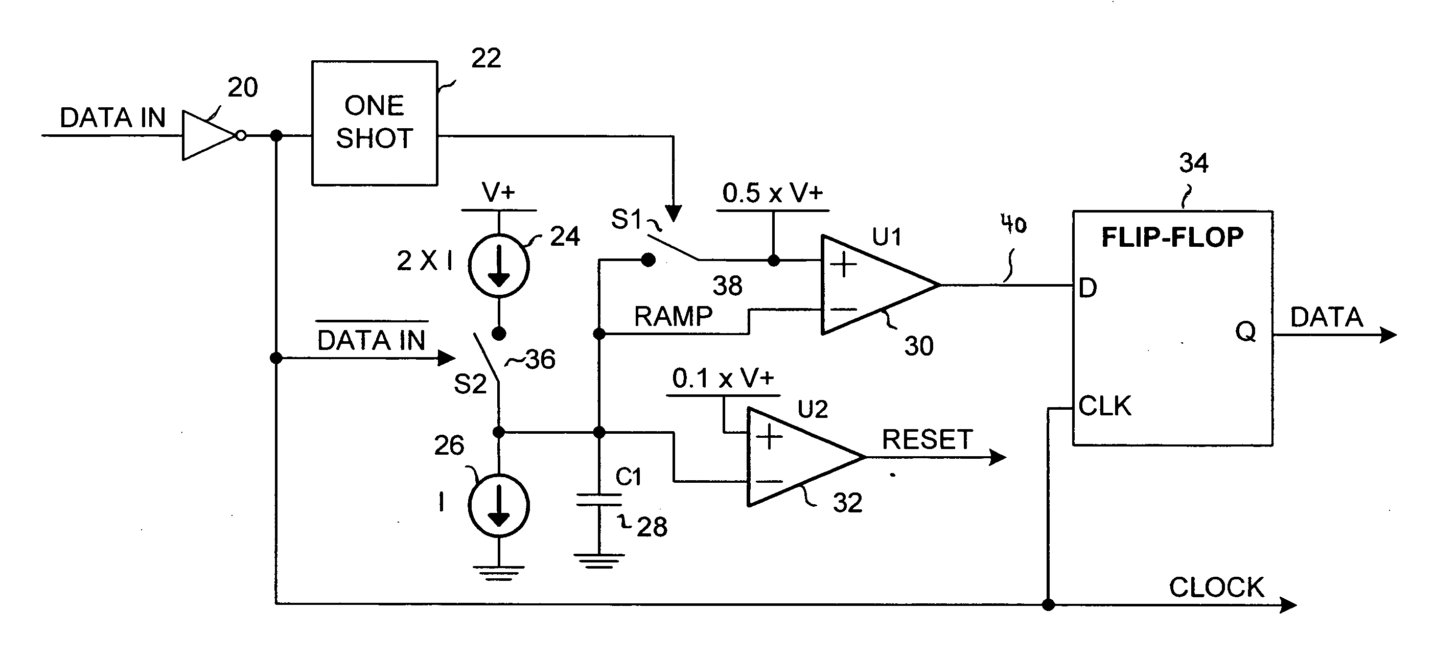
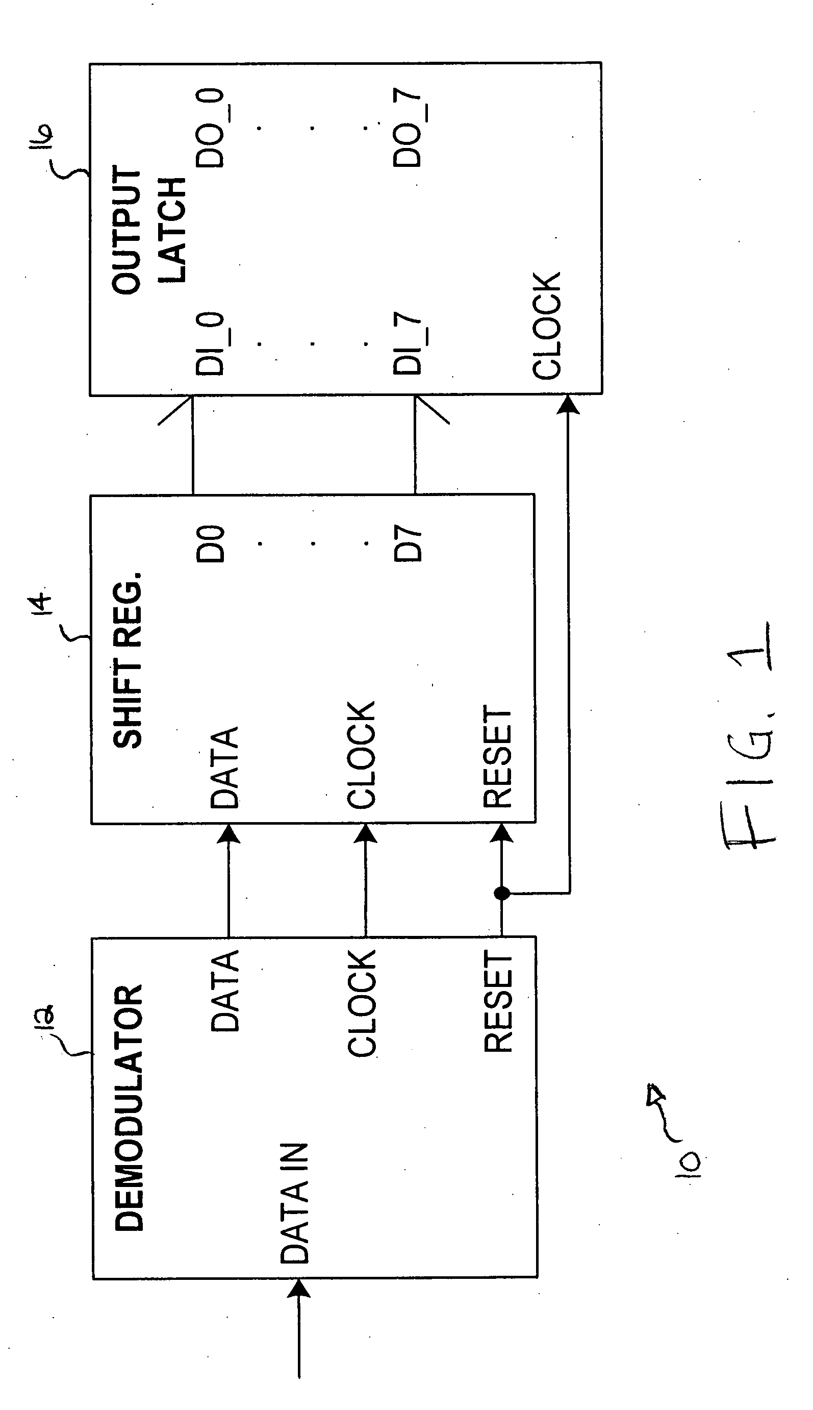
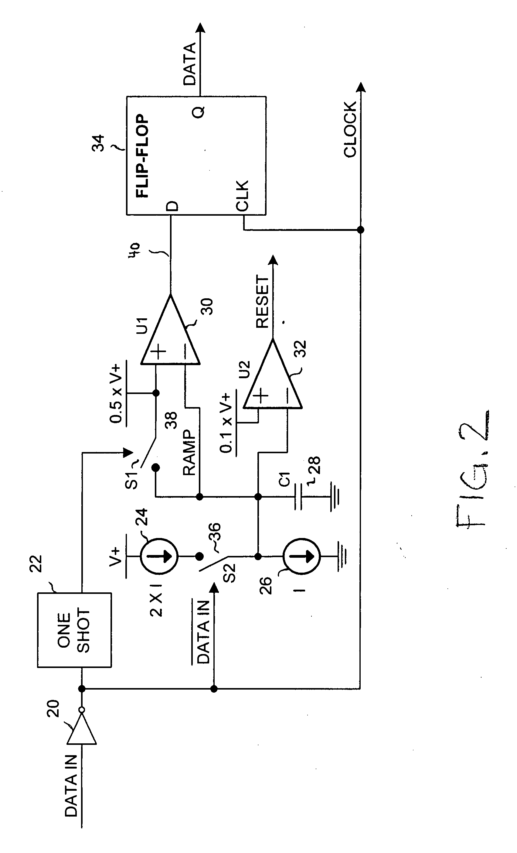
[0015]In various embodiments, the present invention provides an interface and protocol between a control circuit (e.g., microprocessor, microcontroller, ASIC, or other suitable control circuit) and a peripheral circuit (e.g., memory chip, power management chip, or other suitable peripheral circuit). The control interface and protocol utilize a single line (e.g., wire, trace, or other suitable connector) over which control data is provided in a logic signal between the control circuit and the peripheral circuit. The state of the logic signal on the single wire is determined, for each bit of data, by the proportion of time that the signal on the line is low compared to the proportion of the time that the signal on the line is high, for example, for a period defined from one...


PUM


Abstract

In one embodiment, a method for a control interface includes: receiving a signal conveying bits of information over a single line; and for each bit of information, comparing the proportion of time that the signal on the single line is low versus the proportion of time that the signal on the single line is high for a respective bit period defined from one operative edge of the signal to the next operative edge of the signal in order to determine a logic value for that bit of information.

Description

BACKGROUND[0001]1. Field of Invention[0002]The present invention relates to control operations for electronic devices, and more particularly, to a control interface and protocol.[0003]2. Description of Related Art[0004]Modern electronic devices typically include multiple integrated circuit (IC) devices or “chips,” each of which performs one or more respective functions, such as, for example, processing, data storage, sensing, power management, etc. The various IC devices may be connected together by wiring (traces) on a printed circuit board (PCB). For many electronic devices, the peripheral chips (such as power management IC devices) are controlled by the microprocessor. The connection requirements for digital control range from simple (a single setting) to complex (multiple outputs with multiple set points). It is often desirable to minimize the number of interconnecting interfaces or wires between the controlling microprocessor and the peripheral chips in order to reduce PCB spac...

Claims


Application Information

Patent Timeline
IPC IPC(8): H03K9/08G01R29/02
CPCH04L25/0264H03K5/125
Inventor KLEIN, JONATHAN
Owner SEMICON COMPONENTS IND LLC
Why Eureka
Try Eureka