
Image forming apparatus and method of correcting deviation of shooting position

a technology of image forming apparatus and shooting position, which is applied in the direction of printing mechanism, spacing mechanism, printing, etc., can solve the problems of inability to perform detection with high accuracy, difficult to accurately scan test patterns, and difficult to distinguish black ink from electrostatic belts, etc., to achieve accurate detection simple configuration, and accurate correction of deviation of liquid droplet shooting positions

Inactive Publication Date: 2008-09-18
RICOH KK
View PDF19 Cites 37 Cited by
  • Summary
  • Abstract
  • Description
  • Claims
  • Application Information

AI Technical Summary

Benefits of technology

The patent text describes an image forming apparatus and method for detecting and correcting the deviation of liquid droplets ejected from a recording head. The technical effects of this invention include the ability to accurately detect and correct the shooting position of liquid droplets, even when the colors of the ink and the transfer belt are close to each other. Additionally, the invention can detect and correct the failure of nozzles in the ejection process, without the need for expensive sensors or filters. The method also includes the use of a reference pattern composed of plural independent liquid droplets and a pattern to be measured, which are arranged in parallel in a scanning direction of the recording head.

Problems solved by technology

However, as described in Patent Documents 1 through 3, when the test patterns are formed on the transfer belt and the colors for detecting the test patterns are detected or picked up, it is difficult to scan the test patterns accurately because their color difference is small depending, for example, on the combination of the color of the transfer belt and that of the ink.
Therefore, when the test patterns are detected only by the reflection of the colors and the pickup by the pickup unit, it is difficult to distinguish black ink from the electrostatic belt.
As a result, it is not possible to perform the detection with high accuracy.
In addition, since the apparatus is required to have a filter for each color, the variety of sensors and filters increases to thereby cause high cost.
In case that the detection accuracy is improved, the combination of the ink to be used and the transferring member is limited.
Moreover, when a laser beam is used to detect the failure of nozzles, an extremely limited point is scanned.
Therefore, since the scanning is susceptible to small foreign matter particles and flaws on the transferring member, detection accuracy may be lowered.
The RGB sensor needs at least units for scanning each color, thereby increasing costs.
In addition, since the apparatus recognizes the test patterns as two-dimensional images, it needs a relatively high performance processing system compared with a case where one-dimensional images are recognized, thereby increasing costs.
As a result, it is not possible to detect the test patterns with high accuracy.
Furthermore, if the test patterns are formed on a plain paper as a recording medium through which so-called ink permeates so that they are scanned by an optical sensor, blurring may occur due to the permeation of the ink and the patterns could be washed out.
As a result, it is not possible to detect the shooting positions accurately.

Method used


Image

  • Image forming apparatus and method of correcting deviation of shooting position
  • Image forming apparatus and method of correcting deviation of shooting position
  • Image forming apparatus and method of correcting deviation of shooting position

Examples


Embodiment Construction

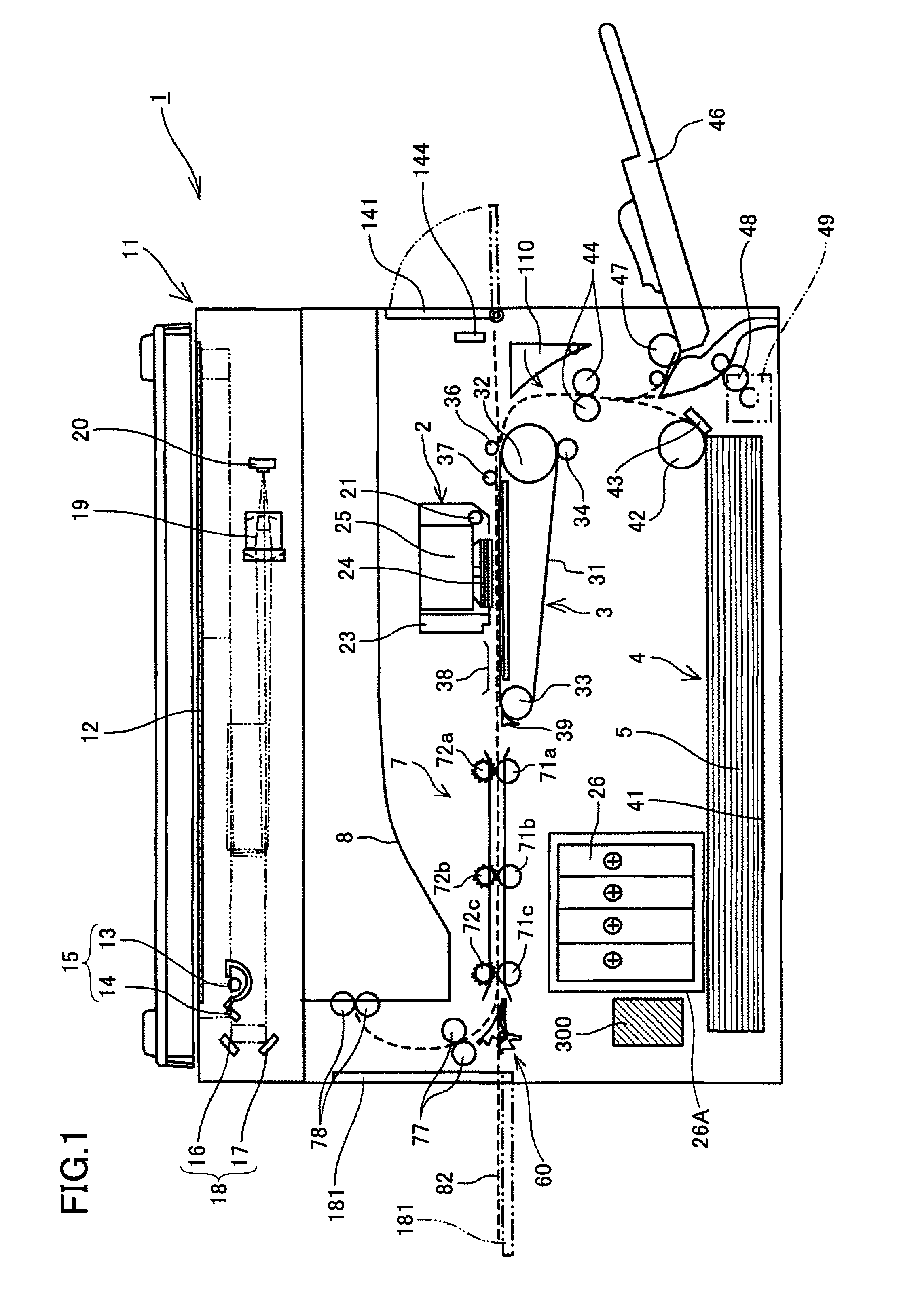
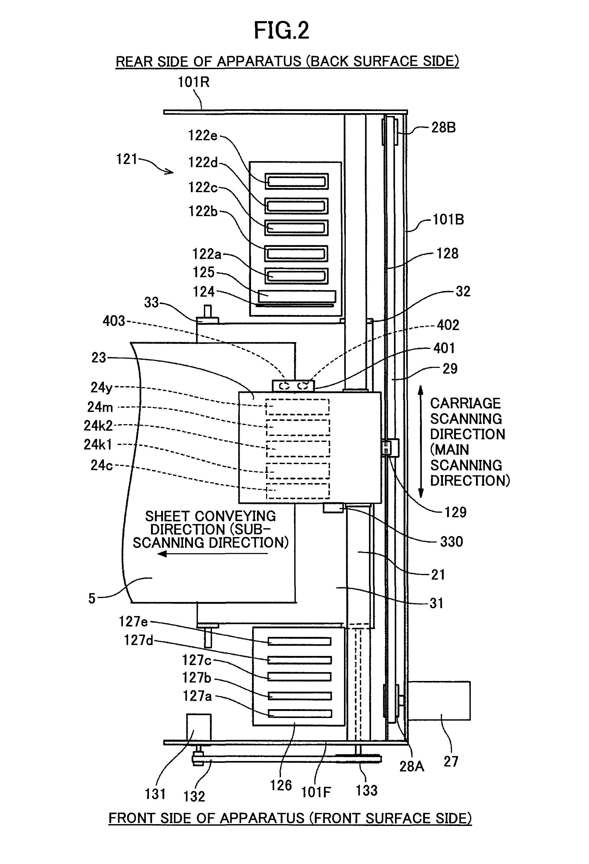
[0061]Next, referring to the accompanying drawings, a description is made of an embodiment of the present invention. FIGS. 1 through 3 describe a general outline of an example of an image forming apparatus according to the embodiment of the present invention. Note that FIGS. 1, 2, and 3 are a schematic view showing an entire configuration of the image forming apparatus, a plan view showing an image forming section and a sub-scanning conveying section of the image forming apparatus, and a side view showing the image forming apparatus and sub-scanning conveying section in a partially transparent state, respectively.

[0062]The image forming apparatus includes an image forming section (means) 2 that forms images while conveying a sheet, a sub-scanning conveying section (means) 3 that conveys the sheet, and the like inside (in the housing of) an apparatus main body 1. In the image forming apparatus, a sheet 5 is individually fed from a sheet feeding section (means) 4 including a sheet fee...


PUM


Abstract

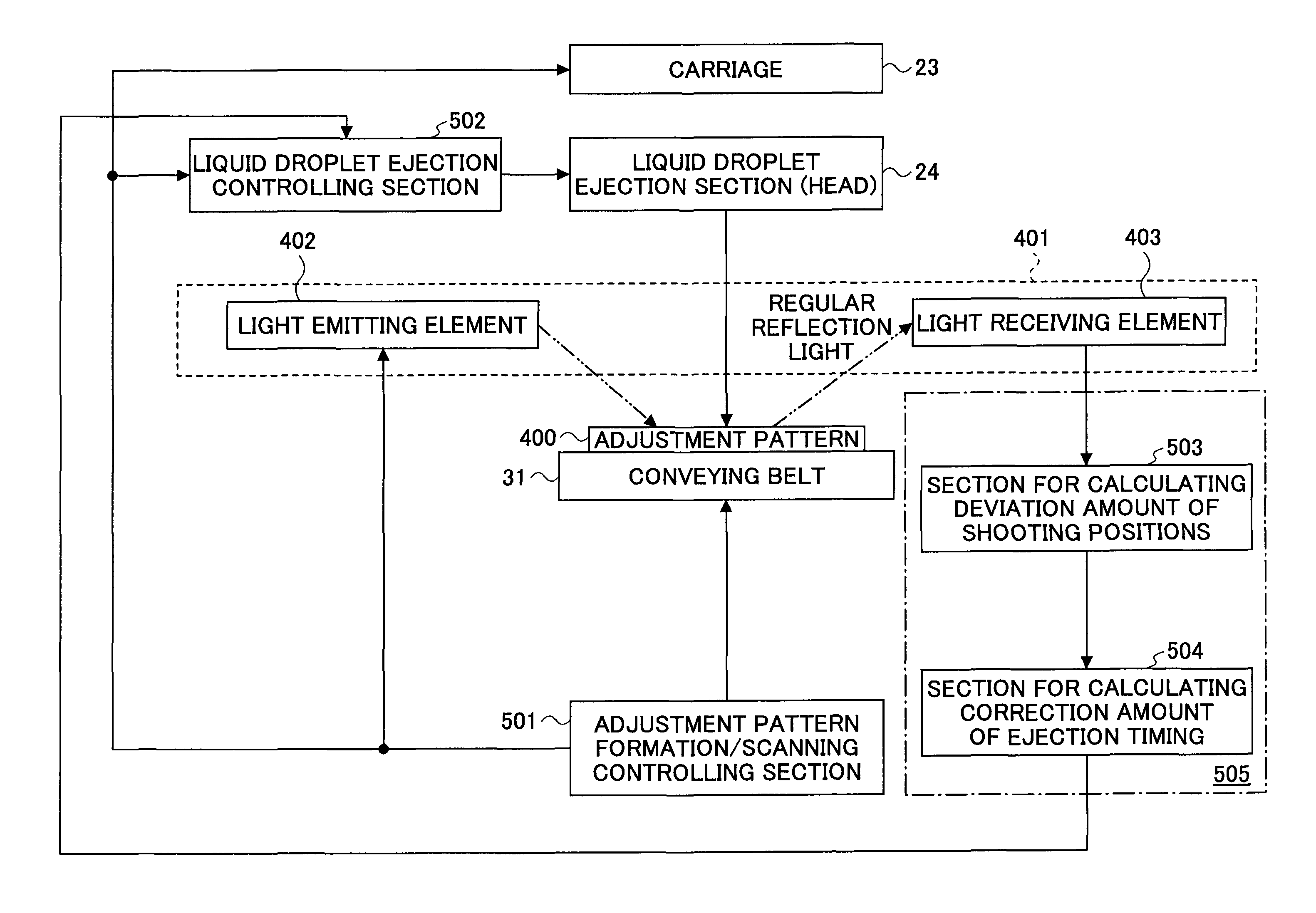
An adjustment pattern, which is composed of a reference pattern made of plural independent liquid droplets and a pattern to be measured made of plural independent liquid droplets ejected under an ejection condition different from the reference pattern, is formed on a water-repellent conveying belt. Then, light is applied to the adjustment pattern to receive the regular reflection light from the adjustment pattern, so that the adjustment pattern is scanned. The distance between the respective patterns is measured based on the measured result. Finally, liquid droplet ejection timing of the recording head is corrected based on the result thus measured.

Description

BACKGROUND OF THE INVENTION[0001]1. Field of the Invention[0002]The present invention relates to an image forming apparatus including a recording head that ejects liquid droplets and a method of correcting the shooting positions of the liquid droplets ejected from the recording head.[0003]2. Description of the Related Art[0004]As an image forming apparatus such as a printer, a facsimile machine, a copier, and a complex machine thereof, there is employed, e.g., a liquid ejection apparatus including a recording head composed of liquid ejection heads (liquid droplet ejection heads) that eject the liquid droplets of recording liquid (liquid) so as to perform image formation. In performing the image formation (that is used synonymously with recording, printing, and imaging), this liquid ejection apparatus causes recording liquid as liquid (hereinafter referred to as ink) to adhere to a sheet, while transferring a medium (hereinafter referred also to as the “sheet,” but it does not limit ...

Claims


Application Information

Patent Timeline
Patent Type & Authority Applications(United States)
IPC IPC(8): B41J29/38B41J29/393
CPCB41J29/393B41J29/38B41J19/207
Inventor YORIMOTO, MAMORUSAWAYAMA, NOBORUKAWABATA, KENICHIMORINO, TETSUHIROTA, TETSUROHAGIWARA, TAKUMI
Owner RICOH KK
Learn More