Heat spreader with high heat flux and high thermal conductivity

a heat spreader and heat flux technology, applied in the field of high heat flux cooling technology for microelectronic systems, can solve the problems of low thermal mass of composite structures, ineffective heat conductors, and high cost of electronics design, and inducing thermal stress

Inactive Publication Date: 2008-09-18
TELEDYNE LICENSING
View PDF23 Cites 121 Cited by
  • Summary
  • Abstract
  • Description
  • Claims
  • Application Information

AI Technical Summary

Benefits of technology

[0015]In more particular embodiments, the effective size of the microporous wicks is between approximately 10 nm and approximately 1,000 nm in radius, while the macroporous wicks may be sized between approximately 1 um and approximately 500 um in radius.
[0016]Advantageously, the microporous wicks, the macroporous wicks, and the coolant of the heat spreader are configured to remove substantially all of the heat generated by the heat source, thereby maintaining the heat source at a constant temperature. The heat source will typically be a microelectronic device.

Problems solved by technology

In addition, composite structures have low thermal mass and are not effective conductors of heat to heat sinks.
The design of low cost COTS (commercial off the shelf) electronics frequently increases heat dissipation, and modern electronics is often packaged with multiple heat sources located close together.
Some systems have local hot spots in particular areas, which induce thermal stress and create performance degrading issues.
Management of such power densities is beyond the capability of traditional cooling techniques, such as a fan blowing air through a heat sink.
Indeed, these power densities even exceed the performance limits of more advanced heat removal techniques, such as a liquid coolant flowing through a cold plate.
These approaches, however, involve heavy components, the thermal conductivity may be too low, mechanical strength can be a limiting factor, and the heat flux may be too low.
Consequently, some new electronic devices are reaching the point of being thermally limited.
As a result, without higher performance thermal management systems, such devices may be hampered by being forced to operate at part of their duty cycle or at a lower power level.

Method used


Image

  • Heat spreader with high heat flux and high thermal conductivity
  • Heat spreader with high heat flux and high thermal conductivity
  • Heat spreader with high heat flux and high thermal conductivity

Examples


Embodiment Construction

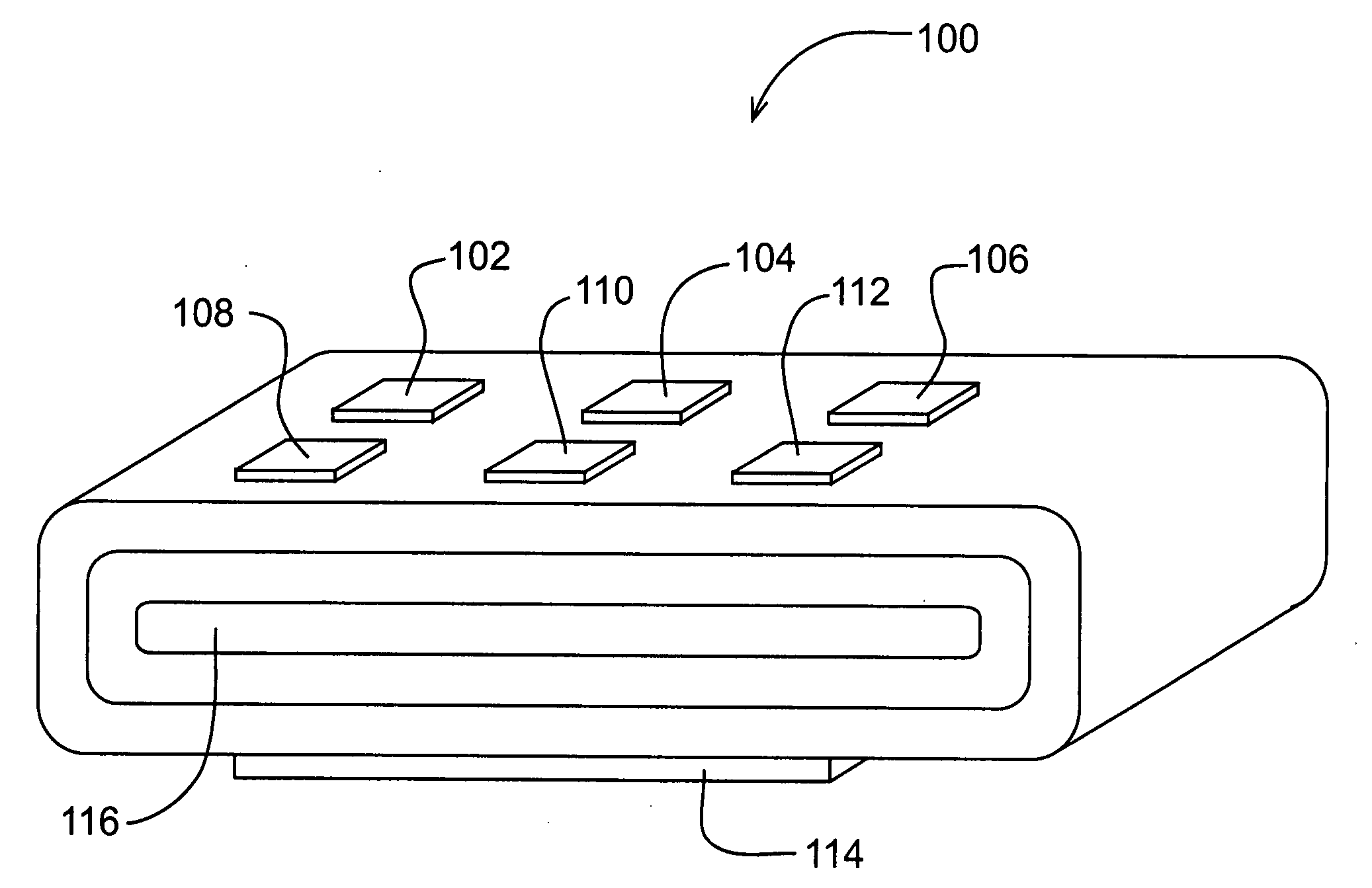
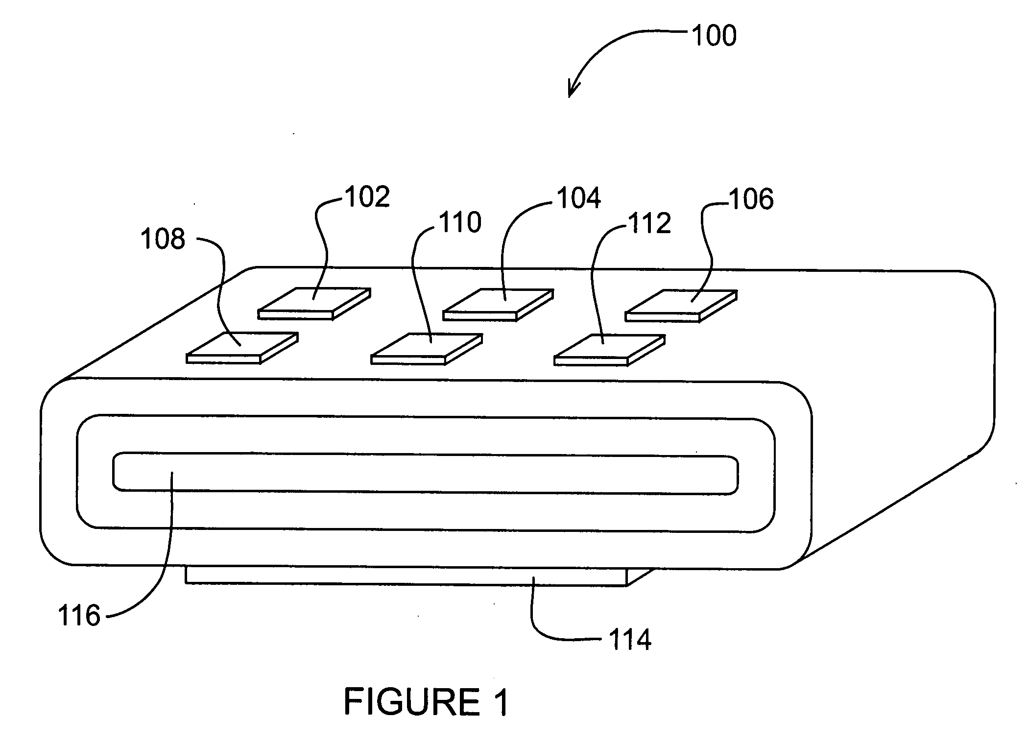
[0025]FIG. 1 is a perspective view depicting a heat spreader constructed according to this invention. The heat spreader 100 transfers heat from a heat source, such as the microelectronic circuit components 102, 104, 106, 108, 110, and 112, to a heat sink 114, using a phase change coolant, which is contained, in both vapor and liquid forms, in a cavity 116.

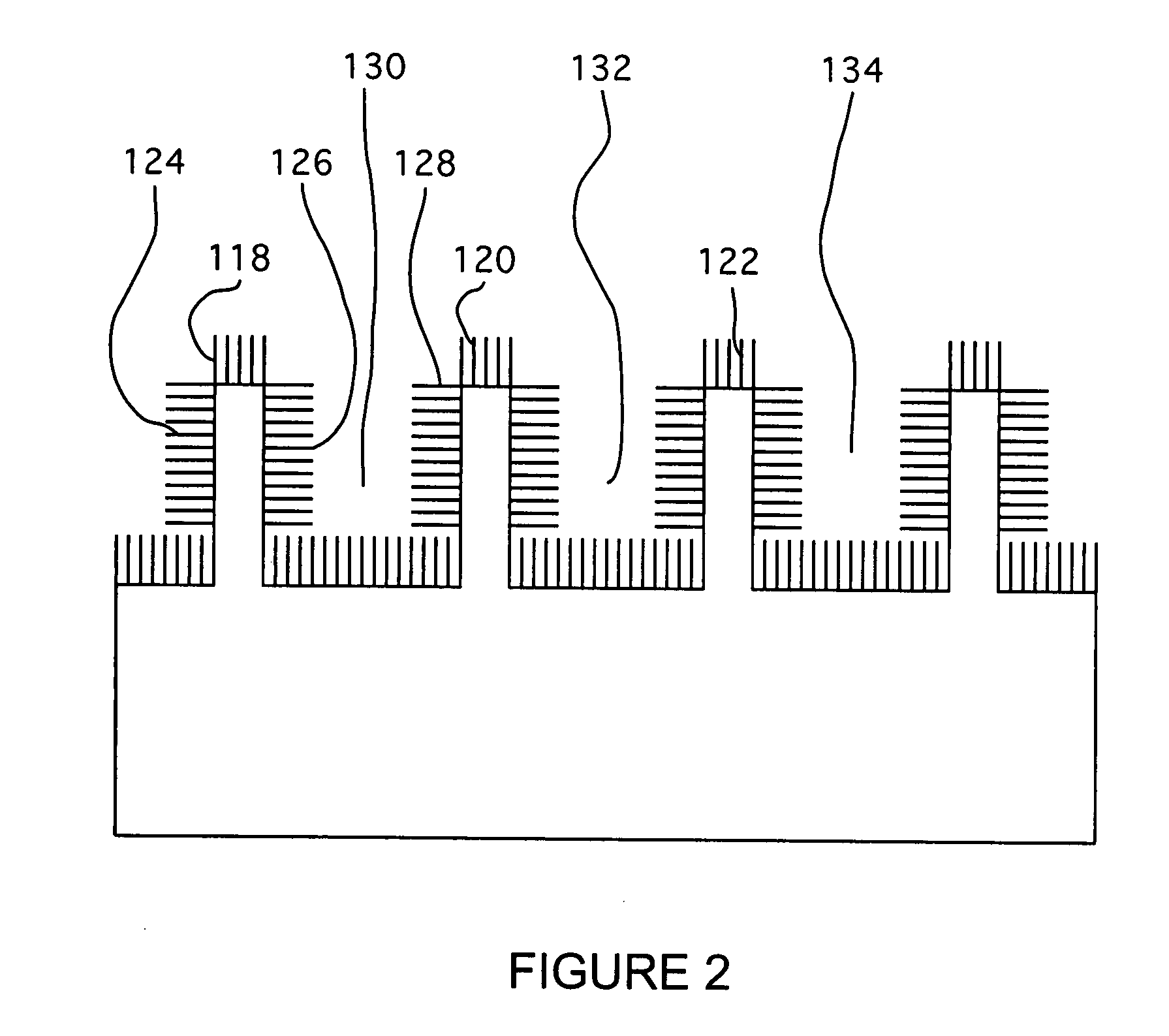
[0026]As depicted by FIG. 2, which is a cross sectional enlarged view of a portion of the heat spreader 100, and by FIG. 3, which is a plan view of the portion of the heat spreader shown in FIG. 2, surrounding the cavity 116 of the heat spreader, which is the primary location for flow of the coolant in vapor form, multiple microporous wicks, such as, for example, the wicks 118, 120, and 122, and the wicks 124, 126, and 128, support flows of the coolant in the liquid phase, via capillary action, from the heat sink to the source.

[0027]In addition, the cavity includes multiple macroporous wicks, such as, for example, the wicks 130, 13...


PUM


Abstract

A heat spreader for transferring heat from a heat source to a heat sink using a phase change coolant, includes an array of cells, each cell having at least one microporous wick for supporting flows of the coolant in the liquid phase, via capillary action, within the spreader from proximate the heat sink to proximate the source and at least one macroporous wick for supporting flows of the coolant, in the liquid and vapor phase, within the spreader from proximate the source to proximate the heat sink.

Description

CROSS REFERENCE TO RELATED APPLICATIONS[0001]This application claims the benefit under 35 USC 119(e) of U.S. Provisional Patent Application No. 60 / 854,007, filed Oct. 23, 2006.GOVERNMENT RIGHTS[0002]The United States Government has rights in this invention pursuant to a contract awarded by the Defense Advanced Research Projects Agency.BACKGROUND OF THE INVENTION[0003]This invention is concerned with techniques for thermal management of electronic devices and more particularly with high heat flux cooling technology for microelectronic systems.[0004]Both the performance reliability and life expectancy of electronic equipment are inversely related to the component temperature of the equipment, with a reduction in the temperature corresponding to an exponential increase in the reliability and life expectancy of the device. Therefore, long life and reliable performance of a component may be achieved by effectively controlling the device operating temperature within the design limits for ...

Claims


Application Information

Patent Timeline
Patent Type & Authority Applications(United States)
IPC IPC(8): F28D15/04H05K7/20
CPCF28D15/0266F28D15/046H01L23/427H01L2924/0002H01L2924/00
Inventor CAI, QINGJUNCHEN, CHUNG-LUNGCHEN, BING-CHUNG
Owner TELEDYNE LICENSING
Why Eureka
Try Eureka