Optical fiber and optical fiber ribbon, and optical interconnection system

a technology of optical fiber and optical fiber ribbon, which is applied in the direction of cladded optical fibre, instruments, optical elements, etc., can solve the problems of inability to cope with the above communication, inability to use fiber in an optical interconnection system, and inability to meet the above communication

Active Publication Date: 2008-09-18
FURUKAWA ELECTRIC CO LTD
View PDF12 Cites 40 Cited by
  • Summary
  • Abstract
  • Description
  • Claims
  • Application Information

AI Technical Summary

Benefits of technology

[0022]It is an object of the present invention to at lea...

Problems solved by technology

With the recent increase of the speed of CPU clock frequencies, occurrence of cross-talk, which is caused by high density wiring, is a problem for the electric transmission scheme.
However, a standard SMF provided in ITU-T (International Telecommunication Union Telecommunication Standard Sector) G.652 can not cope with the above communication because a large bending loss occurs when this SMF is accommodated in an apparatus.
Howe...

Method used


Image

  • Optical fiber and optical fiber ribbon, and optical interconnection system
  • Optical fiber and optical fiber ribbon, and optical interconnection system
  • Optical fiber and optical fiber ribbon, and optical interconnection system

Examples


Embodiment Construction

[0037]Exemplary embodiments of an optical fiber according to the present invention are explained below. The present invention is not limited to the embodiment.

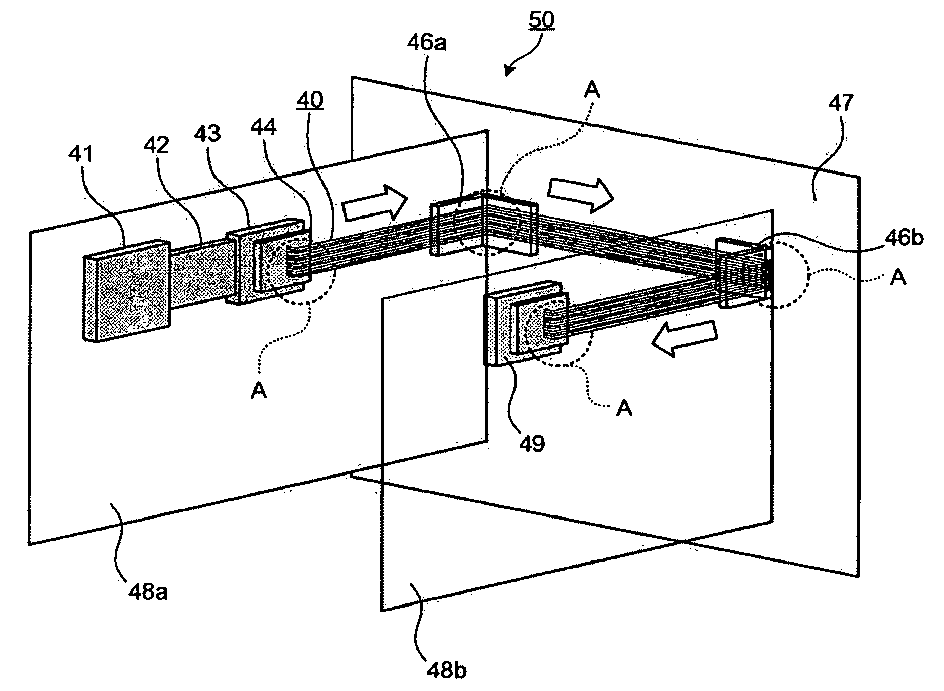
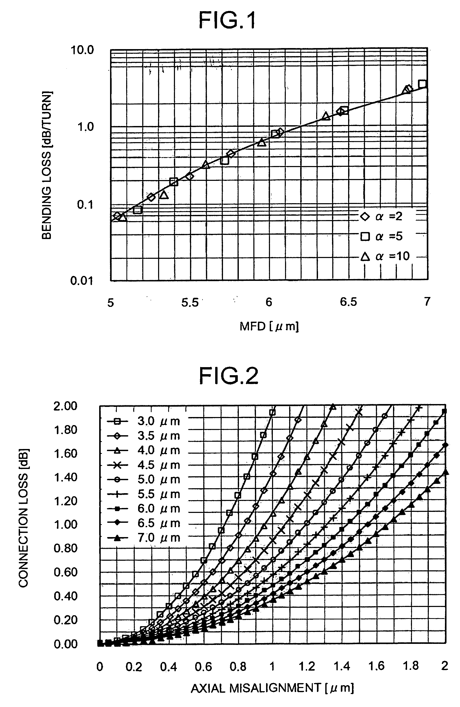
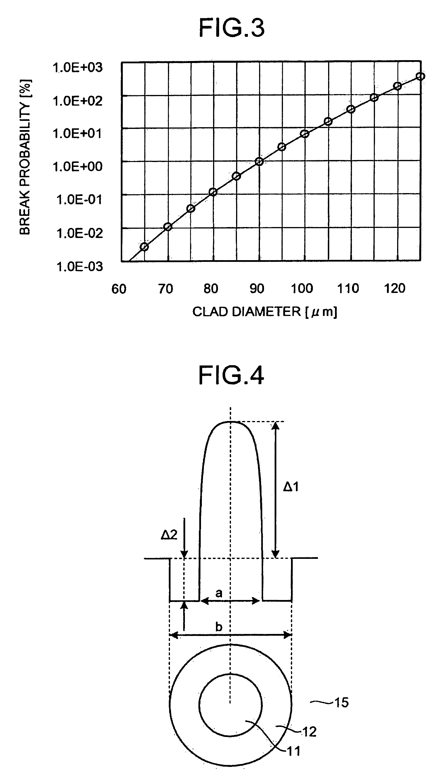
[0038]An optical fiber according to the embodiments of the present invention enables high-speed optical transmission that exhibits a small loss over a 1.3 μm band by single-mode operation at a wavelength of 1,250 nm. A mode field diameter of the optical fiber for a wavelength of 1,300 nm is 6.5 μm or larger and, thereby, a connection loss generated between optical fibers can be reduced and construction of an optical interconnection system is facilitated. Simultaneously, a bending loss for the wavelength of 1,300 nm generated when the optical fiber is bent at a radius of curvature of 1.5 mm is 1 dB / turn and, thereby, flexible wiring and compact accommodation of the optical fiber are enabled. Specific description will be given below.

[0039]When a silica-based optical fiber is used for in-apparatus optical wiring, it is required t...


PUM


Abstract

An optical fiber, made of silica-based glass, comprising a core and a cladding. The optical fiber having a mode field diameter of 6.5 μm or larger at a wavelength of 1300 nm, transmitting light with a wavelength of 1250 nm in a single mode, and having a bending loss of 1 dB/turn or smaller at a wavelength of 1300 nm when the optical fiber is bent with a curvature radius of 1.5 mm.

Description

CROSS-REFERENCE TO RELATED APPLICATIONS[0001]This application is a continuation of PCT / JP2007 / 067055 filed on Aug. 31, 2007, the entire content of which are incorporated herein by reference.BACKGROUND OF THE INVENTION[0002]1. Field of the Invention[0003]The present invention relates to an optical fiber typically used for optical wiring inside an apparatus.[0004]2. Description of the Related Art[0005]Schemes used for signal transmission inside an apparatus can be two types: electric transmission scheme and optical interconnection scheme. With the recent increase of the speed of CPU clock frequencies, occurrence of cross-talk, which is caused by high density wiring, is a problem for the electric transmission scheme. Therefore, application of a waveform shaping technique, etc., is necessary. As a result, when the electric scheme is employed as the signal transmission scheme in an apparatus, it is known that a transmission distance of about 1 m and a transmission speed of about 10 Gbps ...

Claims


Application Information

Patent Timeline
IPC IPC(8): G02B6/44G02B6/036
CPCG02B6/0281G02B6/03627G02B6/4436G02B6/43G02B6/4403G02B6/03644
Inventor SUGIZAKI, RYUICHISHIMOTAKAHARA, IWAOINABA, HARUMIYAGI, TAKESHI
Owner FURUKAWA ELECTRIC CO LTD
Why Eureka
Try Eureka