Conveyer apparatus

a conveyor and a technology of conveyors, applied in the direction of conveyor parts, electrical equipment, basic electric elements, etc., can solve the problems of increasing const, direct scattering to contaminate the environment and possible contamination of the semiconductor manufacturing line environment, so as to reduce the size of the entire apparatus, reduce the cost, and simplify the structure

Inactive Publication Date: 2008-09-25
HIRATA & CO LTD
View PDF13 Cites 119 Cited by
  • Summary
  • Abstract
  • Description
  • Claims
  • Application Information

AI Technical Summary

Benefits of technology

[0039]According to this configuration, when supporting and conveying a conveyance object in a state where each conveyer (e.g., the upper belt of the endless belt or the upper parts of the rollers) is exposed, guiding a part of the conveyance object (e.g., a guided portion formed to downwardly protrude from the pallet) by using a guide portion of the case enables reliably conveying the conveyance object in the front-and-back direction without displacement in a lateral direction.
[0040]As explained above, ac

Problems solved by technology

Further, a reduction in parallelism or levelness in a lateral direction with time must be adjusted, thus leading to an increase in const.
Furthermore, although the driving mechanism is surrounded by the housing, an abrasion powder or dust produced from, e.g., a slide part scatters from the housing to the outside, and hence an environment of the semiconductor manufacturing line may be possibly contaminated.
Moreover, on a supporting frame side that is not surrounded by the housing, an abrasion power and others produced by sliding may likewise directly scatter to c

Method used


Image

  • Conveyer apparatus
  • Conveyer apparatus
  • Conveyer apparatus

Examples


Embodiment Construction

[0055]Best embodiments of the present invention will now be explained hereinafter with reference to the accompanying drawings.

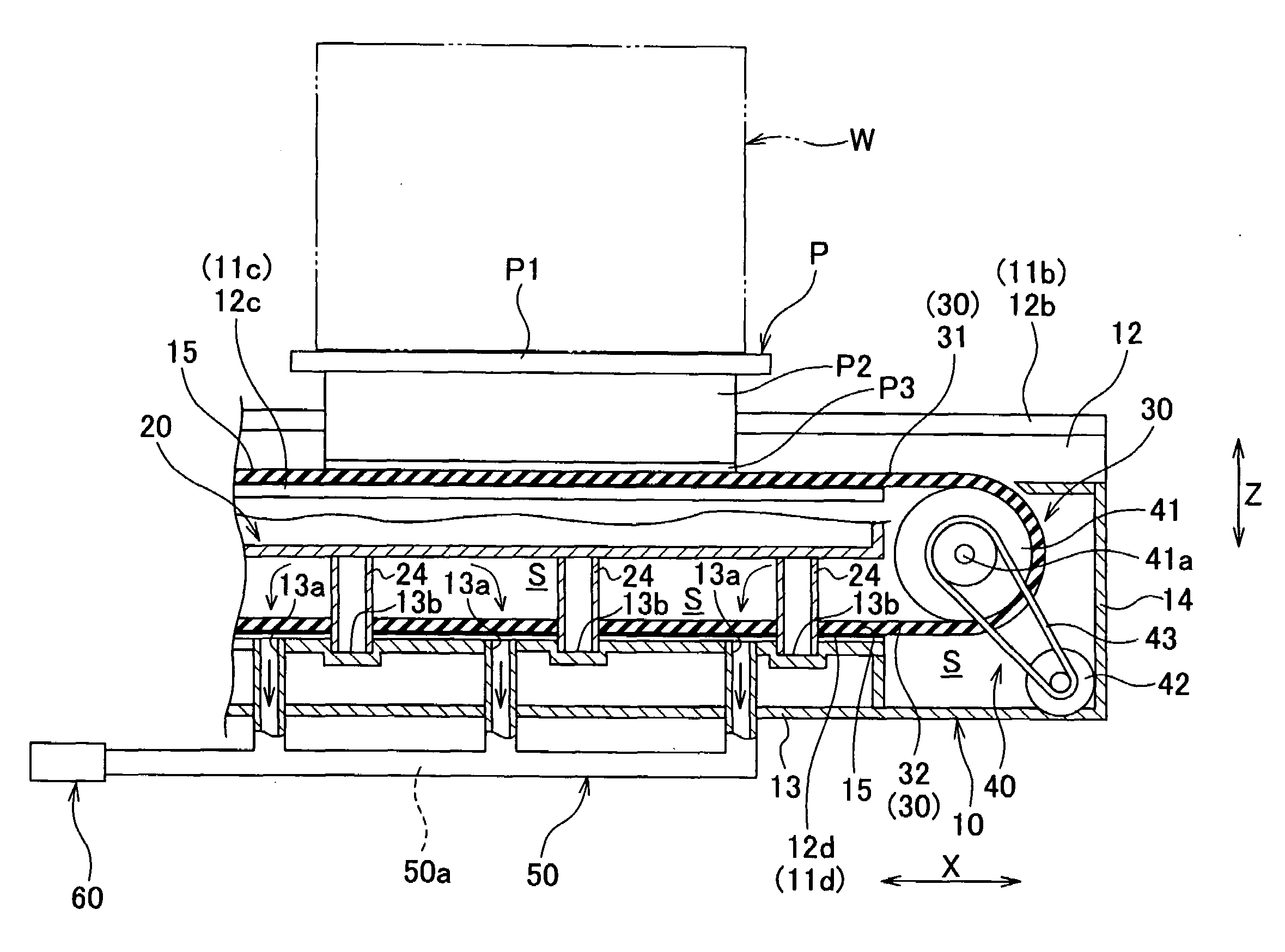
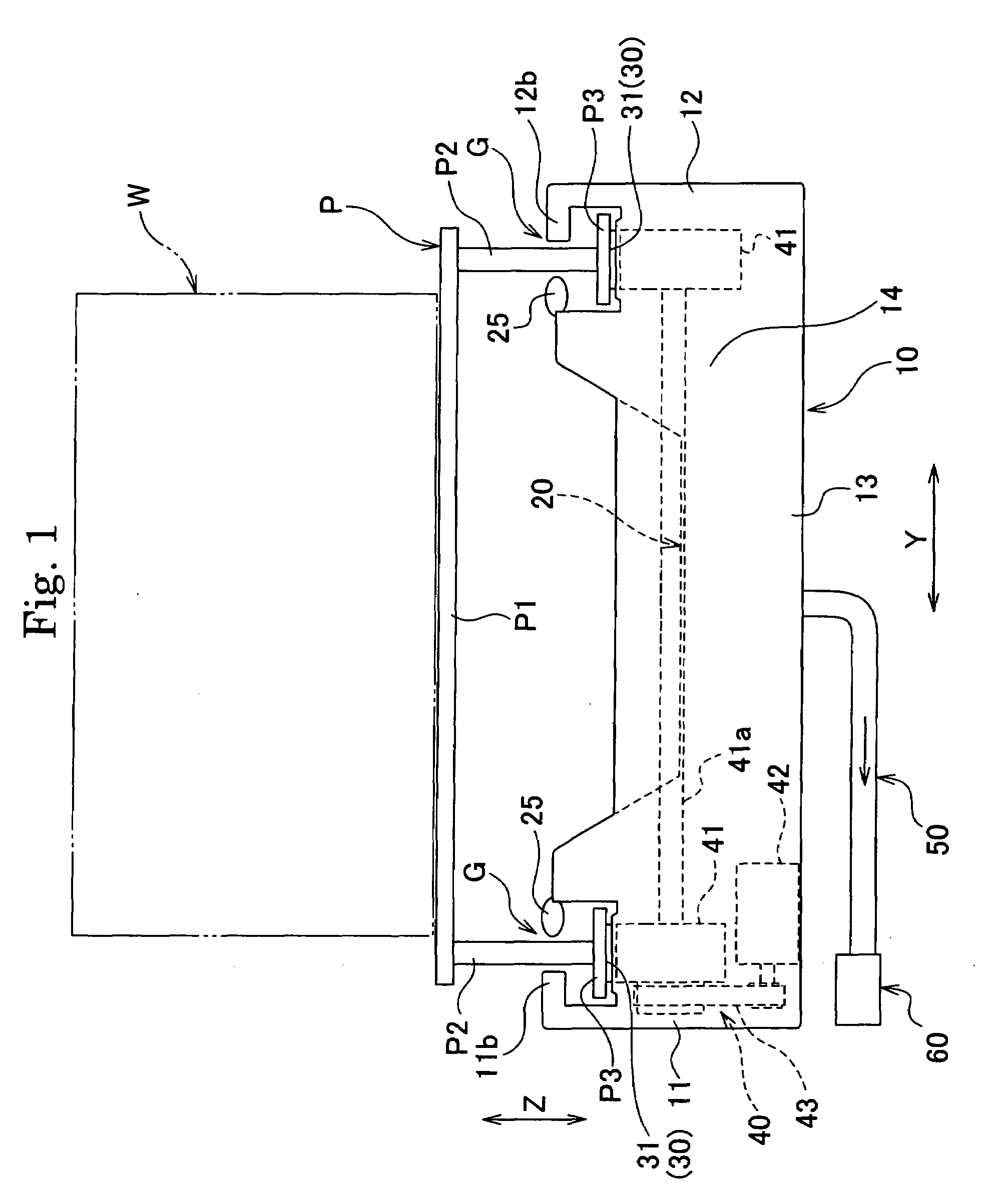
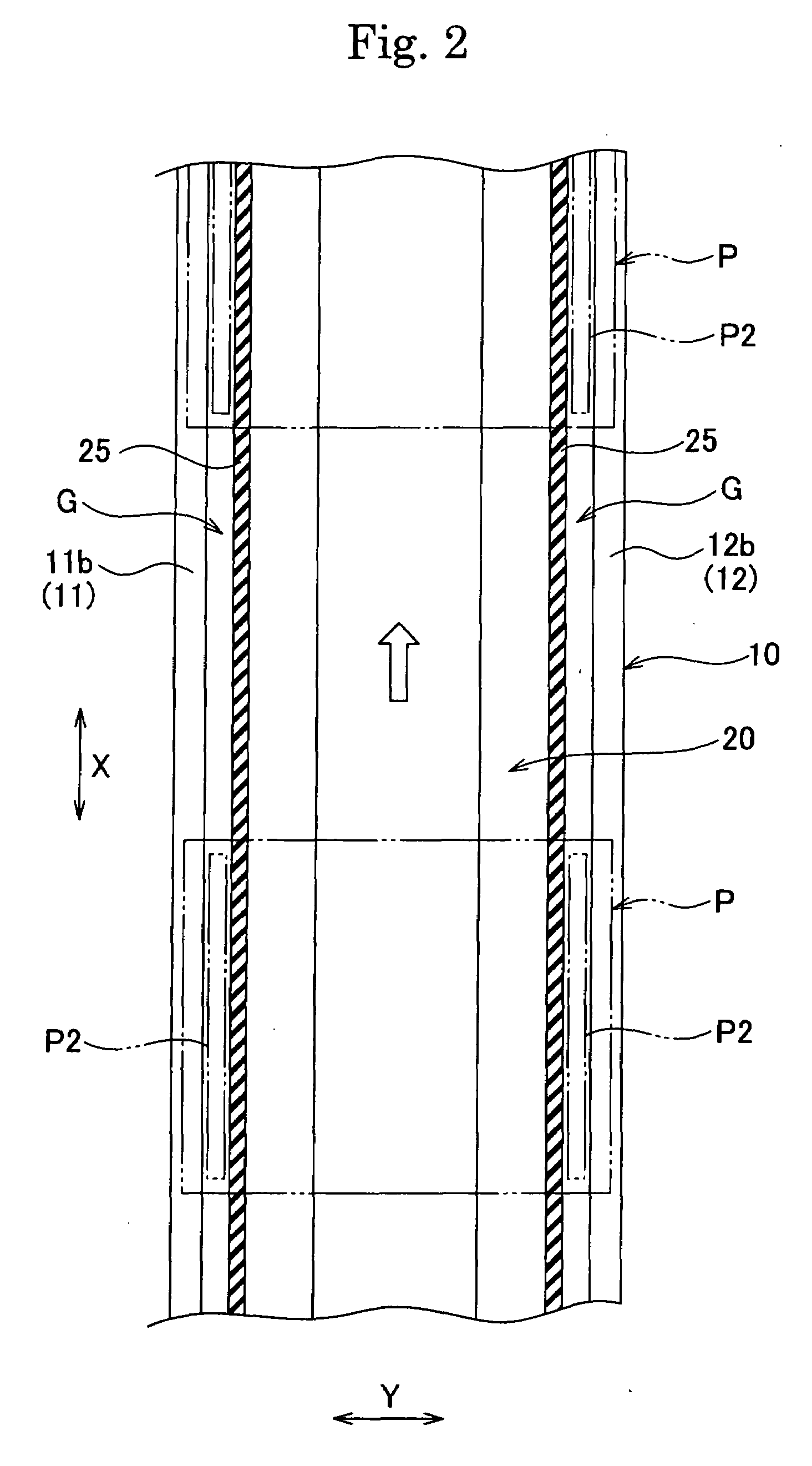
[0056]As shown in FIGS. 1 to 5, this conveyer apparatus includes a lower case 10 forming a part of a case, an upper cover 20 that is coupled with the lower case 10 and forms a part of the case, each endless belt 30 as a conveyer that is accommodated in an internal space S defined by the lower case 10 and the upper cover 20, a driving mechanism 40 that drives each endless belt 30, an exhaust duct 50 and a suction device 60 as sucking means connected with the lower case 10 to suck air in the internal space S, and others.

[0057]It is to be noted that this conveyer apparatus is configured to convey a workpiece W, e.g., a container (FOUP) accommodating a semiconductor substrate and a pallet P supporting the workpiece W as the conveyance object. Here, as shown in FIGS. 1 to 3, the pallet P includes a planar supporting portion P1 that supports the workpiece W, leg po...


PUM


Abstract

A conveyer apparatus according to the present invention includes a case that defines a pair of right and left gap portions each of which has a predetermined width and extends in a conveying direction of a conveyance object, a conveyer that is arranged near or in a region adjacent to each of the pair of right and left gap portions and supported by the case to support and convey the conveyance object, a driving mechanism that is arranged in an internal space of the case to drive each conveyer, and sucking means for sucking air in the internal space. According to this configuration, when the sucking means sucks air in the internal space in the case, an air current flowing into the internal space from the outside through each gap portion is produced, and an abrasion powder or dust generated near, e.g., each conveyer arranged near under each gap portion flows with this air current to be sucked, thus avoiding scattering toward the outside.

Description

BACKGROUND OF THE INVENTION[0001]1. Field of the Invention[0002]The present invention relates to a conveyer apparatus that conveys a workpiece, e.g., an electronic component or a mechanical component, and more particularly to a conveyer apparatus suitable for supporting and conveying an electronic component concerning a semiconductor, e.g., a dedicated container (FOUP) that accommodates, e.g., a semiconductor substrate directly or on a pallet in a clean environment, e.g., a semiconductor manufacturing line.[0003]2. Description of the Related Art[0004]In a conventional semiconductor manufacturing line, when conveying a semiconductor substrate (a wafer) to each processing step (a processing device), a technique of accommodating the plurality of substrates in a dedicated container (FOUP) and conveying this container by using a conveyer apparatus is known. This container is hermetically sealed to maintain the inside thereof in a clean environment. On the other hand, since the environmen...

Claims


Application Information

Patent Timeline
IPC IPC(8): B65G45/22
CPCB65G17/002H01L21/677B65G45/10B65G21/22
Inventor HIRATA, YASUNARI
Owner HIRATA & CO LTD
Why Eureka
Try Eureka