
Method and Circuit for Calculating a Timeout Parameter in a Communication Session

a communication session and timeout parameter technology, applied in the field of method and circuit for calculating the timeout parameter in the communication session, can solve the problems of affecting the user experience of the nfc, inaccurate values of the session timeout parameter, and useless recovery of the llcp session, so as to improve the user experience and improve the user experience. the effect of adjusting the calculation flexibility

Inactive Publication Date: 2008-09-25
NXP BV
View PDF7 Cites 70 Cited by
  • Summary
  • Abstract
  • Description
  • Claims
  • Application Information

AI Technical Summary

Benefits of technology

[0018]It is therefore an object of the present invention to provide a method as defined in the first paragraph and an apparatus as defined in the second paragraph, as well as a computer readable media and a computer programme as defined in the third and fourth paragraph, in which the disadvantages defined above are avoided.
[0024]The provision of the features according to the invention provides the advantage that an appropriate timeout parameter can be automatically determined.
[0025]The measures claimed in claim 2 provide the advantage that the time out parameter comprises a good estimation.
[0026]The measures claimed in claim 3 provide the advantage of a more flexible calculation of the timeout parameter.
[0028]An estimated timeout value can avoid choosing a too long or too short actual timeout parameter, improving the user experience (avoiding too long delays) and the NFC LLCP behaviour. The invention can be applied to all NFC devices supporting the LLCP layer.

Problems solved by technology

A too long GAP_TIMEOUT can introduce a too long delay that can disrupt the NFC user experience, instead a too short GAP_TIMEOUT can make useless the LLCP session recovering because there is not enough time to perform the device discovery (see LLCP specification).
The disadvantage of using a time adder for uncertainty is that this parameter has to be manually set and results inaccurate values for the session timeout parameter that could be either too long or too short.

Method used


Image

  • Method and Circuit for Calculating a Timeout Parameter in a Communication Session
  • Method and Circuit for Calculating a Timeout Parameter in a Communication Session
  • Method and Circuit for Calculating a Timeout Parameter in a Communication Session

Examples


Embodiment Construction

[0032]An embodiment of the present invention is given below.

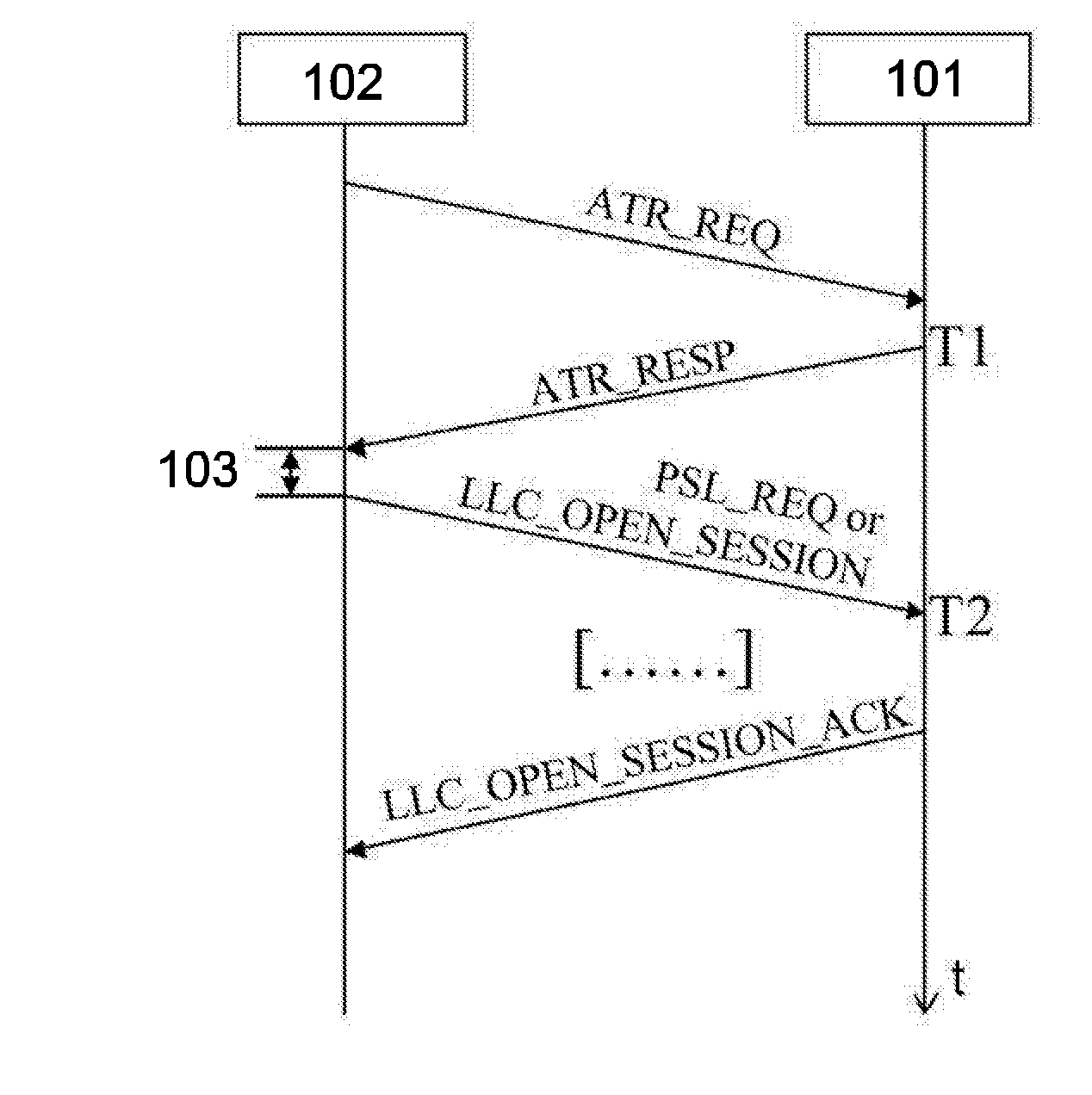
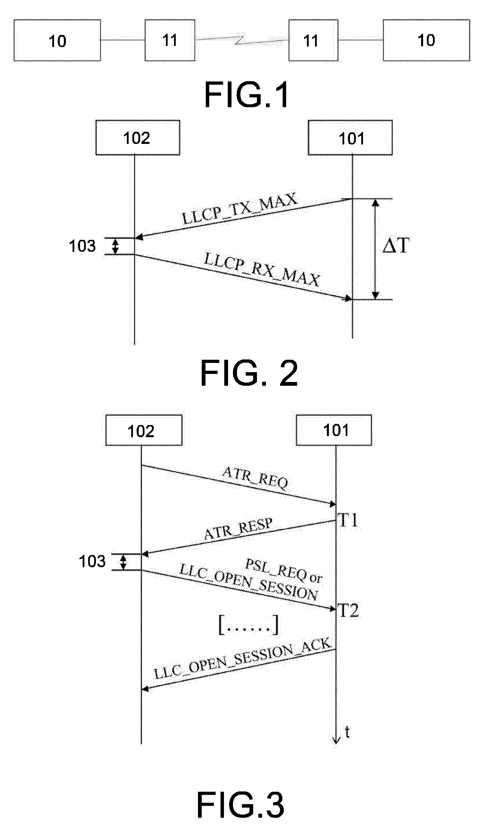
[0033]FIG. 2 shows a target communication device 101 and a initiator communication device 102. Both communication devices 101 and 102 comprise an electronic circuit, preferably an integrated circuit (not shown in FIG. 2) and communication means that are designed for contact-less radio frequency communication. In the present case a communication coil is provided as the communication means for inductive coupling between the two communication devices 101 and 102. However also antenna configurations like mono-pole or multi-pole antennas are applicable. For both devices the circuit is designed to process and to communicate date according to the international standard 18092. The circuit is connected to the communication means of the respective communication device 101 and 102.

[0034]The circuit of the target communication device 101 is designed to perform a time out parameter in a communication session. In the present case a near ...


PUM


Abstract

A method for calculating a timeout parameter in a communication session, comprises the steps of initiating a session; calculating a throughput of the connection during initialisation of the session by measuring a time span between sending and receiving a data packet on a target communication device 101 including a fixed computational time delay of the initiator communication device 102, wherein the packets are smaller than a maximum packet size; calculating a maximum round trip time for the maximum data packet that is possible to be sent and received based on the calculated throughput; and setting a session timeout parameter equal to the calculated maximum round trip time.

Description

FIELD OF THE INVENTION[0001]The invention relates to a method for calculating a timeout parameter in a communication session.[0002]The invention also relates to a circuit designed to calculate a timeout parameter in a communication session according to the above-mentioned method.[0003]The invention further relates to a communication device comprising a circuit according to the preceding paragraph.[0004]The invention further relates to a computer readable media containing a computer executable programme for performing the above-mentioned method.[0005]The invention further relates to a computer programme performing a calculation of a timeout parameter in a near field communication session according to the present invention.BACKGROUND OF THE INVENTION[0006]Identification products such as smart cards and RFID (Radio Frequency IDentification) tags are used widely in fields such as transport (ticketing, road tolling, baggage tagging), finance (debit and credit cards, electronic purse, mer...

Claims


Application Information

Patent Timeline
Patent Type & Authority Applications(United States)
IPC IPC(8): H04J3/00
CPCH04L47/10H04L47/115H04L69/28H04L47/36H04L47/283
Inventor GALLO, FRANCESCO
Owner NXP BV
Learn More