
Analysis Processing Method and Device

a processing method and analysis technology, applied in the field of image processing, can solve problems such as the inability to analyze or inspect with high accuracy, the inability to meet or the inability to analyze or interact with the target biological material with high accuracy, and achieve the effect of high accuracy analysis, efficient analysis, and simple control

Inactive Publication Date: 2008-09-25
UNIVERSAL BIO RESEARCH CO LTD
View PDF0 Cites 7 Cited by
  • Summary
  • Abstract
  • Description
  • Claims
  • Application Information

AI Technical Summary

Benefits of technology

[0037]According to the first aspect of the invention, when one spot is specified, the partial region of the spot is detected, and the spot is specified based on this. Therefore it is not necessary to scan the size of the spot or the shape of the base substance or the winding position altogether, and highly accurate analysis can be performed without scanning the spot and taking an accurate size. Hence there is the effect that highly accurate analysis results can be obtained efficiently for objects for which the position is uncertain.
[0038]According to the second aspect of the invention, there is the effect that using the wound body wound with the linear base substance, makes it possible to analyze with a simple control.
[0039]According to the third aspect of the invention, there is the effect that recognition of a spot for which the position has not been specified, is accurately and efficiently performed.
[0040]According to the fourth aspect of the invention, there is the effect that the size and the central position of the spot is obtained simply and accurately.
[0041]According to the fifth aspect of the invention, there is the effect that determination of the marker is performed accurately, and specifying the position of the detection substance is performed clearly, thus contributing to image analysis.
[0042]Accordingly the sixth aspect of the invention, there is the effect that correction of the base substance (in the direction perpendicular to the direction of the base substance) is favorably performed.

Problems solved by technology

However, if the amount of remaining solution is minute, the encounterability or the reactivity with the target biological material becomes deficient.
On the other hand, if the amount in the respective spot positions is too large, there is the possibility that the solutions are intermixed between the adjacent spots, and with higher densities for the arrangement of large numbers of biological materials, there is the possibility of problems arising in the reliability of the examination or inspection, or in the reactivity with the target biological material.

Method used


Image

  • Analysis Processing Method and Device
  • Analysis Processing Method and Device
  • Analysis Processing Method and Device

Examples


first embodiment

[0093]At first is a description of the analysis processing method and device according to a

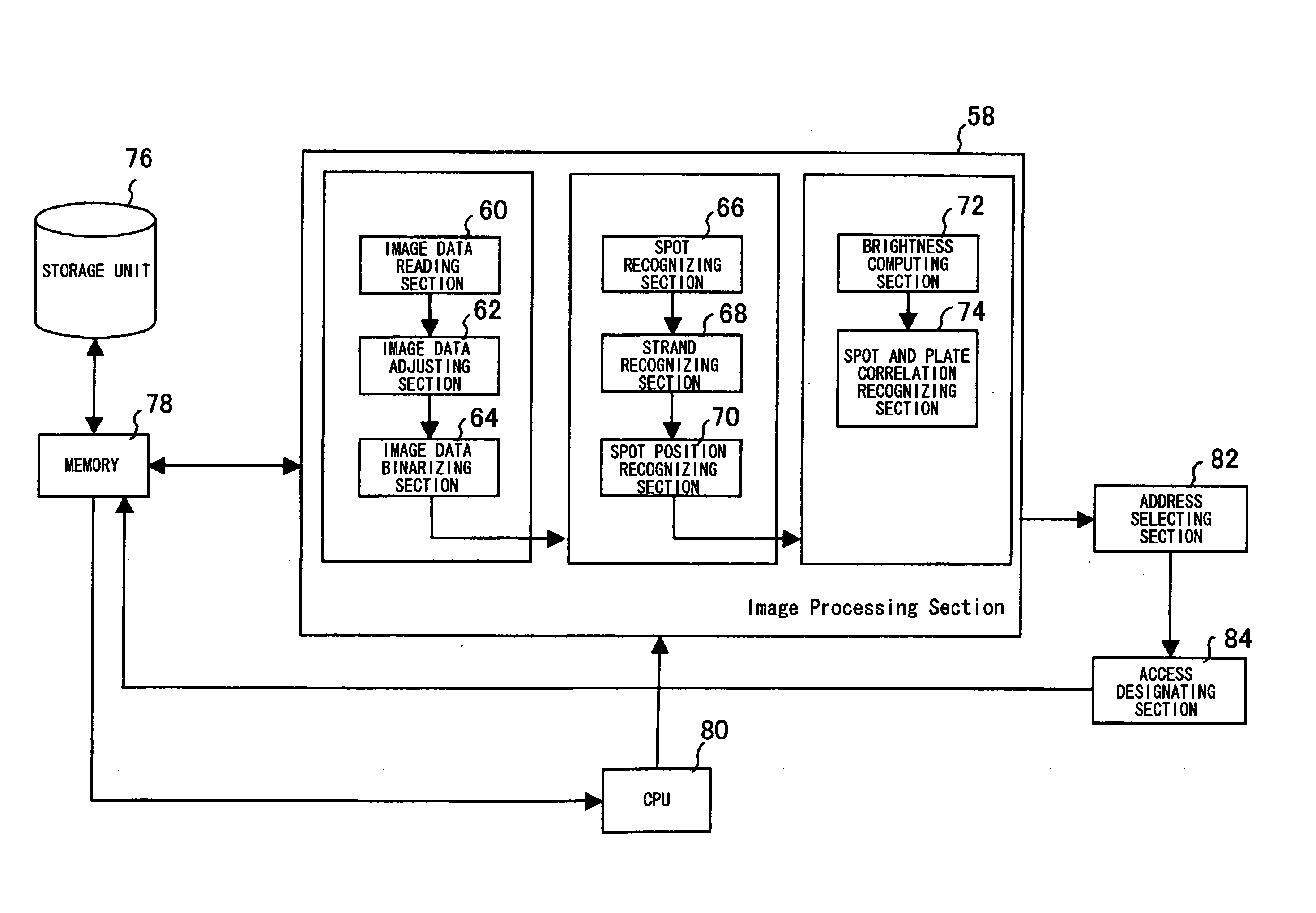
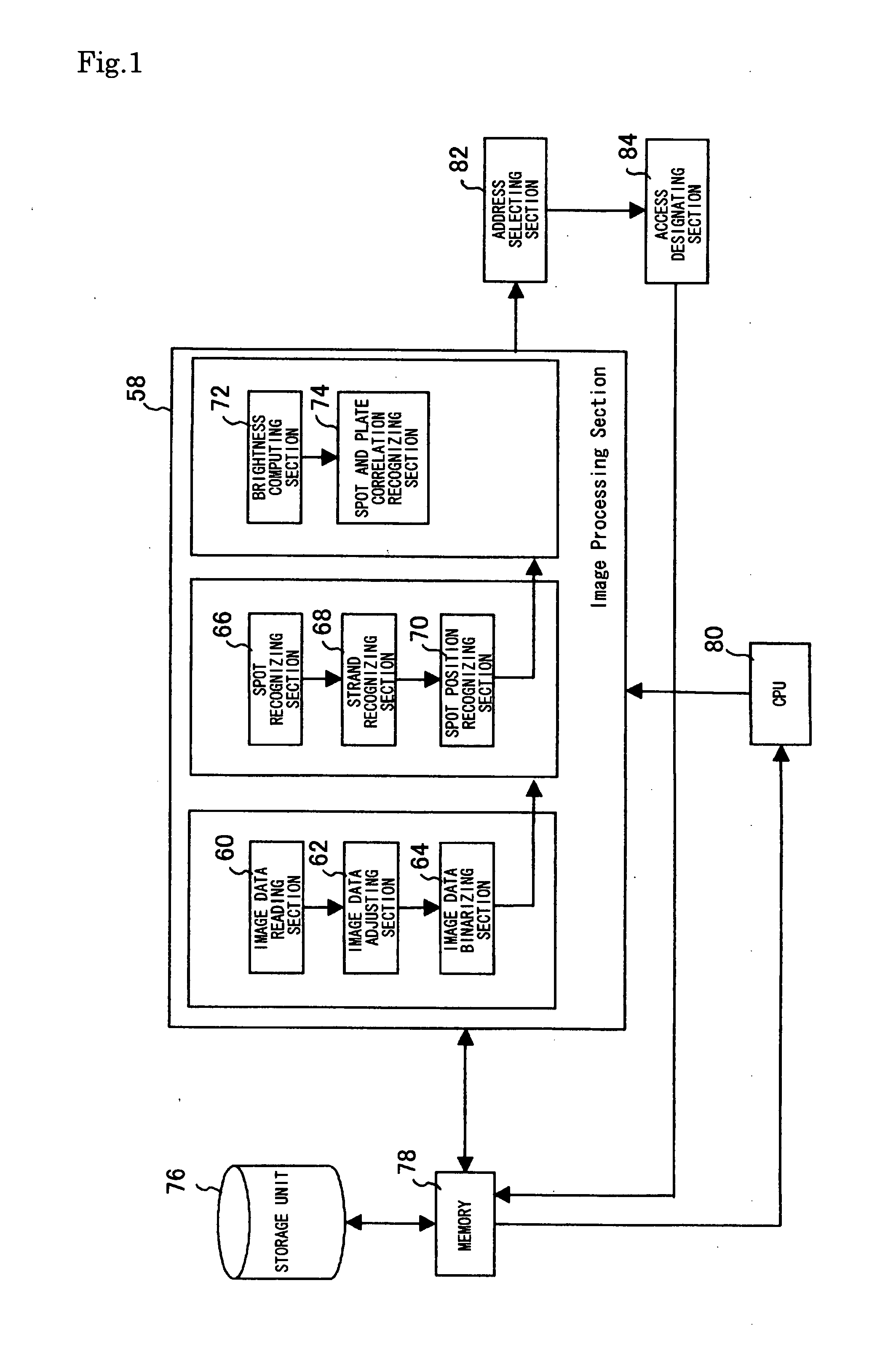
[0094]FIG. 1 shows the analysis processing device. This analysis processing device comprises; an image processing section 58 comprising a program, and a storage unit 76, a memory 78, a CPU 80, an address selecting section 82, and an access designating section 84. The software of the image processing section 58, as shown in FIG. 1 comprises; an image data reading section 60, an image data adjusting section 62, an image data binarizing section 64, a spot recognizing section 66, a strand recognizing section 68, a spot position recognizing section 70, a brightness computing section 72, and a spot and microplate (plate) correlation recognizing section 74.

[0095]The software of the image processing section 58 is made in modules for each of the processing sections, and adopts a form which is highly flexible and extendable (version upgrade). Furthermore regarding; the setting value of the inspection bo...

second embodiment

[0120]Next, is a description of the analysis processing method and device according to a

[0121]FIG. 10 shows the analysis processing device. This analysis processing device comprises; an image processing section 100 comprising a program, and a storage unit 76, a memory 78, a CPU 80, an address selecting section 82, and an access designating section 84. The software of the image processing section 100, as shown in FIG. 10 comprises; an image data reading section 101, a difference computing section 102, a strand position recognizing section 103, a strand direction brightness acquisition section 104, a difference computing section 105, a spot position recognizing section 106, a brightness computing section 107, and a spot and microplate (plate) correlation recognizing section 108.

[0122]The software of the image processing section 100 is made in modules for each of the processing sections, and adopts a form which is highly flexible and extendable (version upgrade). The image data reading...

third embodiment

[0136]Next is a description of the analysis processing method and device according to a

[0137]Regarding the analysis processing contents, the center of a bounding box described in the first embodiment is set at the center of the spot or the marker and stored, and the position of a prediction strand is compensated from a scan in the longitudinal direction of the image afresh, and based on this compensated prediction strand, using the method of the first order difference and the second order difference of the image data used in the second embodiment, the position of the spot is recognized and compensation is performed to determine the spot position.

[0138]FIG. 14 shows the analysis processing device. This analysis processing device comprises; an image processing section 109 comprising a program, and a storage unit 76, a memory 78, a CPU 80, an address selecting section 82, and an access designating section 84. The software of the image processing section 109, as shown in FIG. 14 compris...


PUM


Abstract

The invention relates to image processing, and to a method and device for recognizing the reaction results of a test sample in which various reagents are arranged on a surface, by image analysis, and assay. An object is to provide an analysis processing method and an analysis processing device which can obtain analysis results efficiently and with high accuracy, for objects which are integrated using a wound body which is wound with a linear base substance, and for which positions are uncertain. An analysis processing method for performing analysis based on optical information from a wound object which is wound with a linear base substance in which biological substances of previously determined types are immobilized, and a plurality of these immobilized spots are arranged at previously determined positions, includes: detecting a partial region belonging to the spots, by means of optical information obtained by scanning a surface of the wound body; specifying the spots belonging thereto, based on the detected partial region for the detected spots; and performing analysis of the spots based on the optical information from the specified spots.

Description

TECHNICAL FIELD[0001]The present invention relates to image processing, and to a method and device for recognizing the reaction results of a test sample in 4 which various reagents are arranged on a surface, by image analysis, and assay. The invention is used for manufacturing arrays of three dimensions such as a columnar shape, on which are arrayed samples containing various biological material such as for example nucleic acid, polynucleotides, olygonucleotides, proteins, sugars, immunity substances and the like, and is particularly useful in the fields where it is necessary to perform monitoring and processing using these arrayed various samples (specimens), for example in various fields of; chemistry including biological chemistry, medicine, health, pharmaceuticals, food stuffs, agriculture, animal husbandry, marine products, and technology.BACKGROUND ART [0002]Heretofore, planar arrays on which for example different genetic specimens of several thousand various types, or biologi...

Claims


Application Information

Patent Timeline
IPC IPC(8): G06K9/00
CPCG06K2209/07G06K9/00G06V2201/04G06V10/44
Inventor TAJIMA, HIDEJIIKEDA, HIDEOSEGAWA, OSAMU
Owner UNIVERSAL BIO RESEARCH CO LTD
Learn More