Memory management device and method, program, and memory management system

a memory management and memory management technology, applied in the field of memory management devices and methods, can solve the problems of complex control of multi-value value processing, limited address for data storage, and low access speed

Inactive Publication Date: 2008-09-25
CANON KK
View PDF5 Cites 67 Cited by
  • Summary
  • Abstract
  • Description
  • Claims
  • Application Information

AI Technical Summary

Benefits of technology

[0016]According to the first aspect of the present invention, when writing data in a storage device having memory units different in access speed, it is possible to allocate a storage area accessible at a high speed to the data without limiting addresses where the data is to be written.
[0017]The control unit can designate the predetermined access speed as an access speed in the page allocation information, thereby causing the data to be written in the first memory unit.

Problems solved by technology

However, the multi-value flash memory requiring complicated control for multi-value processing is disadvantageous in that access speed is lower.
For this reason, in a case where the host system writes data at a desired access speed, addresses for data storage are limited.
Further, this method is undesirable for the interface of a file system assuming the use of a generally standard interface.
Furthermore, even if the interface of the FAT file system is provided with a command for disposing a desired file in the high-speed area, the client of the file system cannot always recognize or discriminate a file to be accessed at a high speed as such.
Therefore, it is difficult to dispose a file to be accessed at a high speed in the high-speed area.

Method used


Image

  • Memory management device and method, program, and memory management system
  • Memory management device and method, program, and memory management system
  • Memory management device and method, program, and memory management system

Examples


first embodiment

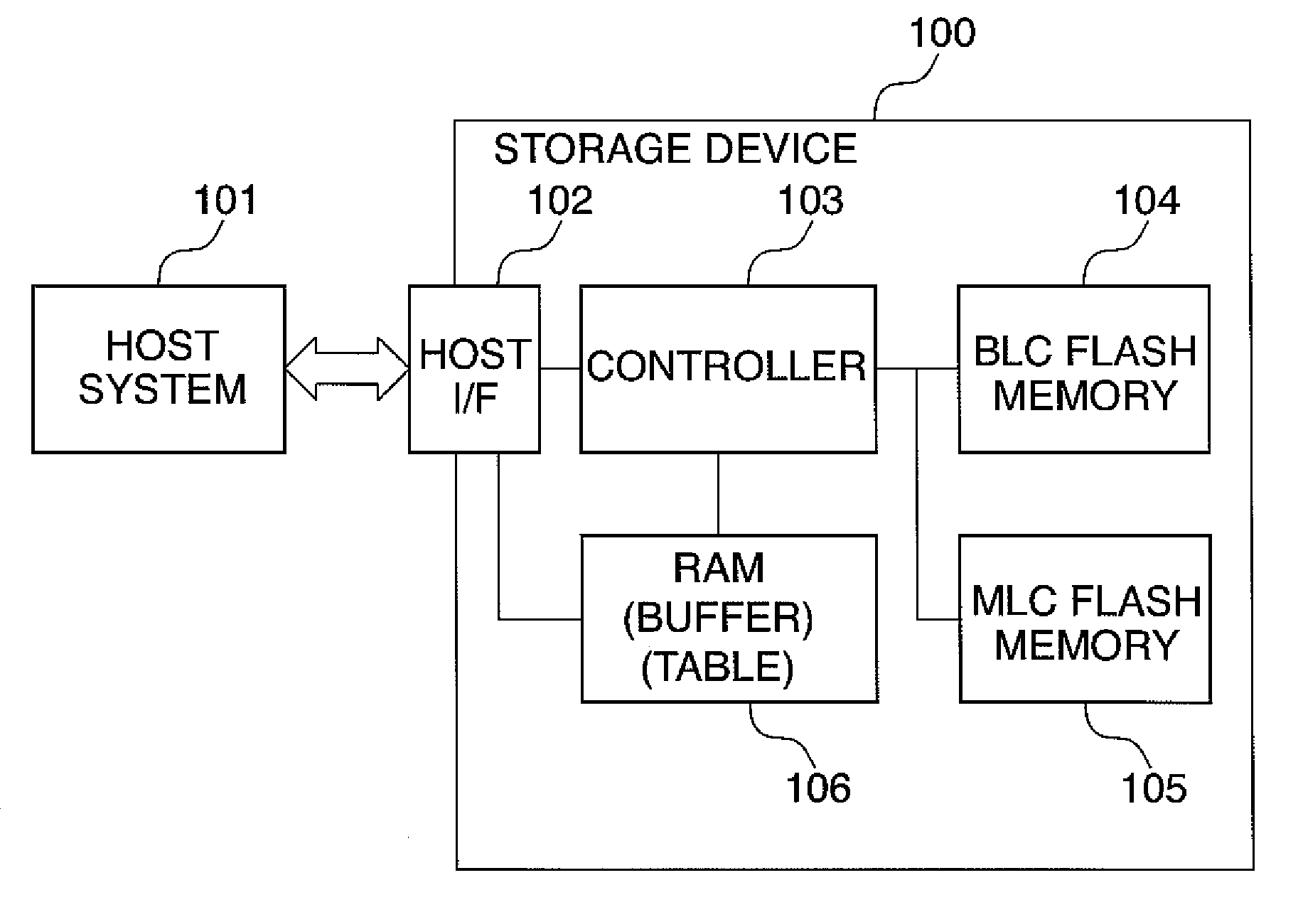
[0054]FIG. 1 is a block diagram of a memory management system including a memory management device according to the present invention.

[0055]As shown in FIG. 1, the memory management system is comprised of a host system 101, and a storage device 100, for example. The host system 101 incorporates a file system, not shown, and a block device driver, not shown,

[0056]The host system 101 is implemented e.g. by a CPU (Central Processing Unit) of an apparatus, such as a digital camera which the storage device 100 can be incorporated in or attached to. The storage device 100 serves as a block device for the host system 101. A block device is a storage medium into which is input data blocks each formed by a plurality of bytes as units, and is implemented e.g. by a flash memory.

[0057]The storage device 100 is comprised of a host interface (interface) 102, a controller 103, a BLC (Binary Level Cell: binary type) flash memory 104, an MLC (Multi-Level Cell: multi-value type) flash memory 105, and...

second embodiment

[0171]Next, a description will be given of the present invention.

[0172]A memory management device according to the second embodiment is identical in configuration (FIGS. 1 to 5) to the memory management device according to the first embodiment. Therefore, a description will be given of only different points from the first embodiment while designating identical elements by the same reference numerals, and omitting detailed description thereof.

[0173]As shown in FIG. 10, in the above described first embodiment, the garbage collection process is executed in timing synchronous with execution of the data writing process by the storage device 100. In the present second embodiment, the garbage collection process is executed not during data writing, but executed as a background process asynchronously with the data writing process. This makes it possible to reduce processing for data writing, thereby relatively shortening processing time for data writing.

[0174]Now, a description will be given...

third embodiment

[0181]Next, a description will be given of the present invention.

[0182]A memory management device according to the third embodiment is identical in configuration (FIGS. 1 to 5) to the memory management device according to the first embodiment. Therefore, a description will be given of only different points from the first embodiment while designating identical elements by the same reference numerals, and omitting detailed description thereof.

[0183]In the above described first embodiment, as shown in FIG. 17, when the host system 101 designates a page speed using the “Page rate” command, only processing for changing the bit value of the speed designation 312 of the page allocation information entry 310 of the associated page is performed.

[0184]In the third embodiment, when the host system 101 designates a page speed using the “Page rate” command, the bit value of the speed designation 312 of the page allocation information entry 310 of the associated page is changed, and at the same t...


PUM


Abstract

A memory management device which is capable of allocating a memory unit accessible at a higher speed to data which is stored in a storage device having memory units different in access speed, without being limited in an storage area. The storage device comprises a BLC flash memory accessible at a predetermined access speed, an MLC flash memory accessible at a lower access speed than the predetermined access speed, a controller, and a RAM. The controller manages the BLC flash memory and the BLC flash memory in units each formed by a plurality of physical pages, and writes data in the physical pages, and the RAM holds page allocation information in which logical pages designated when writing data and the physical pages are associated with each other.

Description

BACKGROUND OF THE INVENTION[0001]1. Field of the Invention[0002]The present invention relates to a memory management device and method, in which a storage device having memory units different in access speed is used as a block device, and arbitrary data can be assigned to memory units having high-speed access speed, a program for implementing the memory management method, and a memory management system.[0003]2. Description of the Related Art[0004]Conventionally, flash memories have been widely used as storage media for digital cameras and the like. The flash memories include a binary type configured such that each memory cell takes two values and a multi-value type configured such that each memory cell takes more than two values. The multi-value flash memory having a larger storage capacity per unit cell than the binary flash memory is advantageous in that it is possible to increase capacity at low costs. However, the multi-value flash memory requiring complicated control for multi-...

Claims


Application Information

Patent Timeline
Patent Type & Authority Applications(United States)
IPC IPC(8): G06F12/00
CPCG06F3/0601G06F12/0246G06F2212/7205G06F2003/0692G06F2212/7202G06F12/08G06F3/0673G06F12/02G06F13/16
Inventor TAGAWA, YOJIRO
Owner CANON KK
Why Eureka
Try Eureka