

Reciprocating to rotary mechanical conversion device
a technology of mechanical conversion device and rotary drive, which is applied in the direction of toothed gearing, belt/chain/gearing, gearing, etc., can solve the problems of imminent failure, short period of time, and inability to operate such a gear train for an engine, so as to minimize the impact of the engagement process and short period of time
- Summary
- Abstract
- Description
- Claims
- Application Information
AI Technical Summary
Benefits of technology
Problems solved by technology
Method used
Image

Examples
Embodiment Construction
[0026]The present invention will now be described more fully in detail with reference to the accompanying drawings, in which the preferred embodiments of the invention are shown. This invention should not, however, be construed as limited to the embodiments set forth herein; rather, they are provided so that this disclosure will be complete and will fully convey the scope of the invention to those skilled in the art.
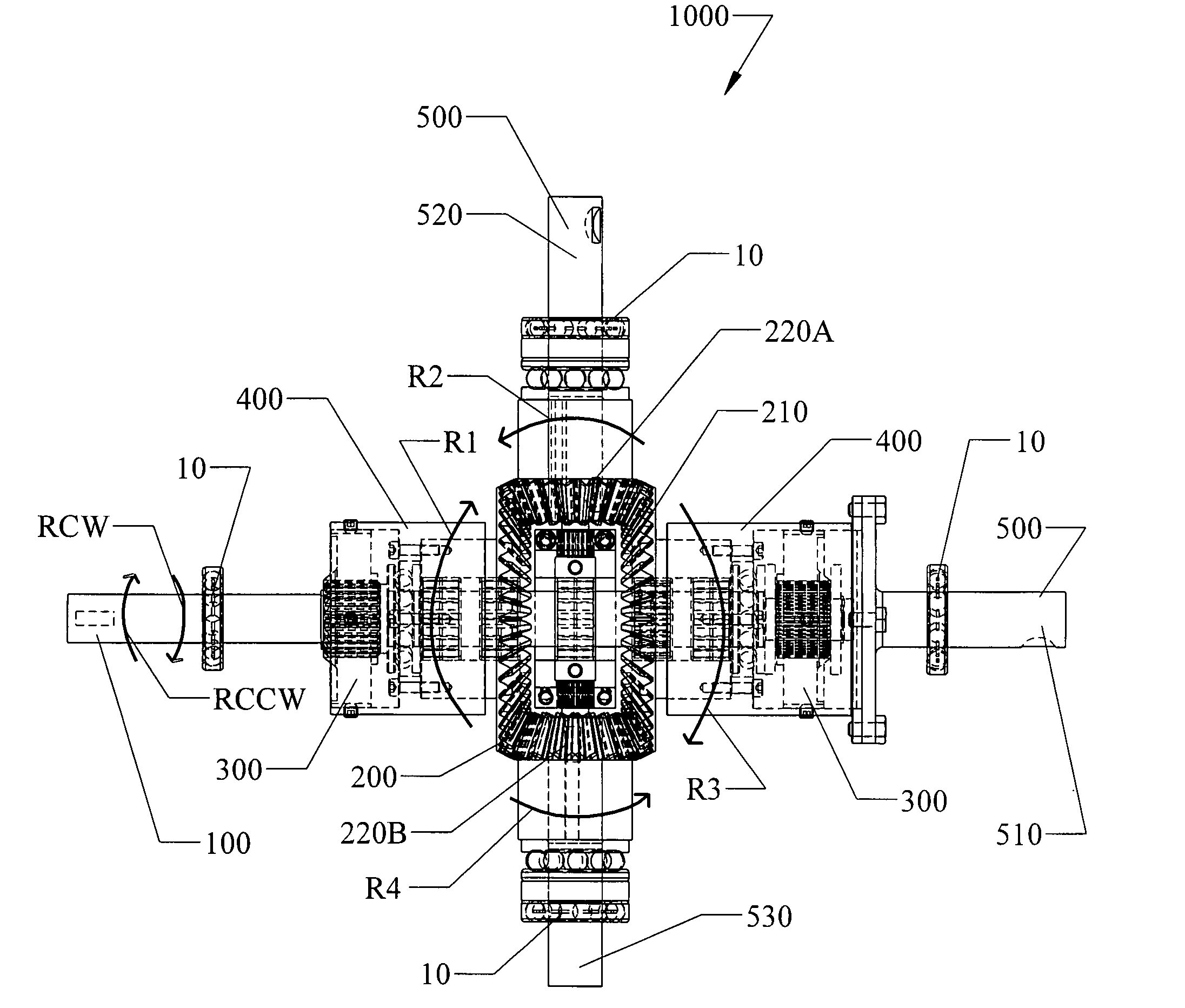
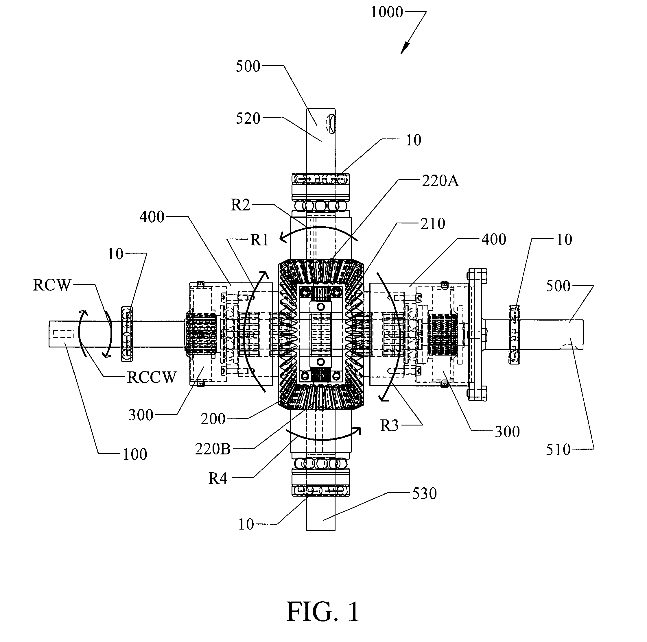
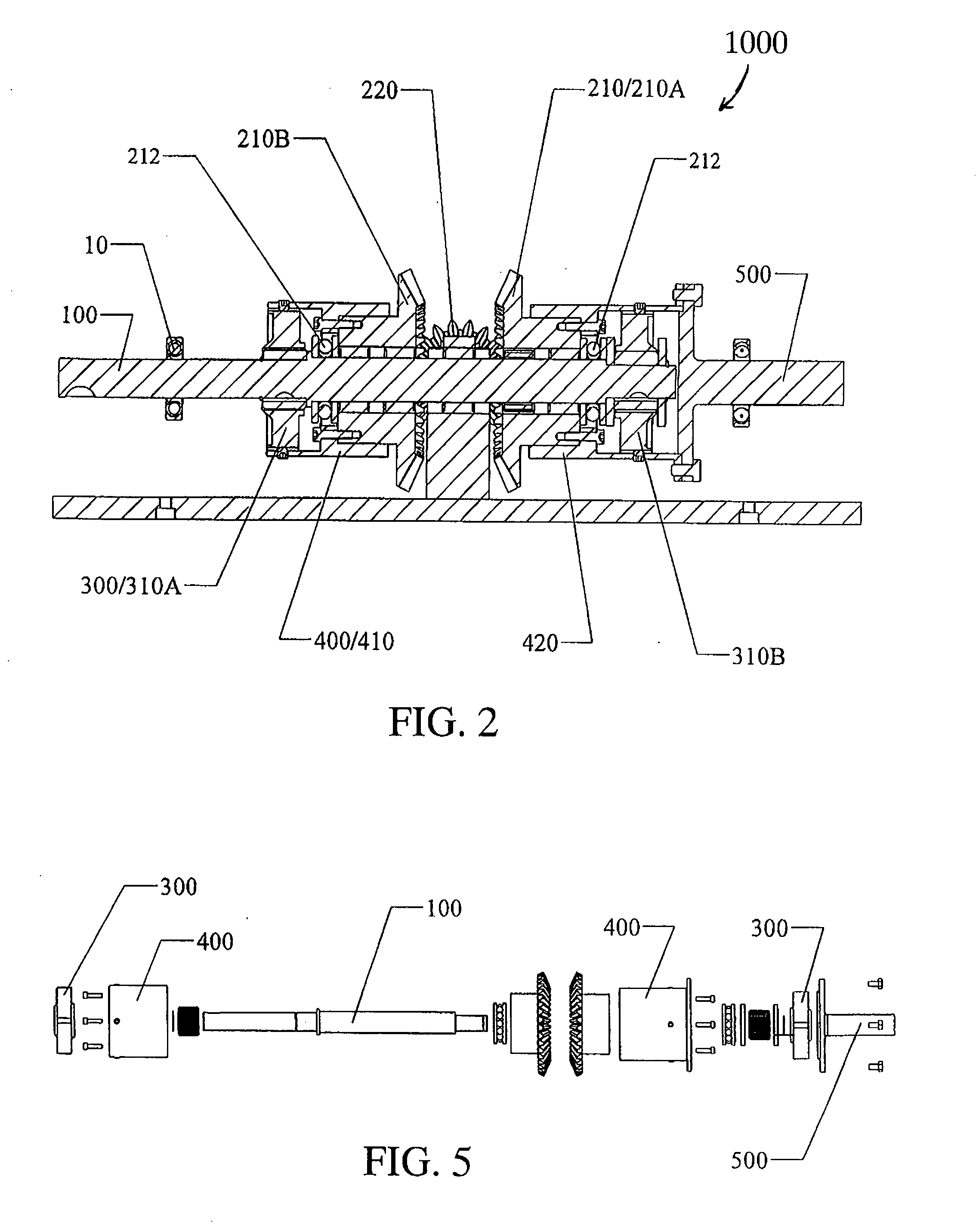
[0027]FIGS. 1-5 illustrate a mechanical conversion device (MCD) 1000 according to the invention. The MCD 1000 comprises an input shaft 100, a set of gears 200, at least one pair of one-way or overrunning clutches 300, a pair of couplers 400, individually designated as 410 and 420, and an output shaft 500. The input shaft 100 is connected at a far end (not shown) to a toroidal reciprocating engine and transmits a counter-rotating oscillatory motion into the gear train assembly. The counter-rotating motion is indicated by the two directional arrows Rcw for clockwise motion...
PUM
 Abstract
Description
Claims
Application Information