
Distributed architecture for a gas-turbine starter/generator

a technology of starter/generator and distributed architecture, which is applied in the direction of electric generator control, vehicle energy devices, transportation and packaging, etc., can solve the problems of occupying a large space and presenting a significant weight, and achieve the effect of reducing weight and the bulk thereof, and being easy to dismantl

Active Publication Date: 2008-10-02
SAFRAN ELECTRICAL & POWER
View PDF19 Cites 40 Cited by
  • Summary
  • Abstract
  • Description
  • Claims
  • Application Information

AI Technical Summary

Benefits of technology

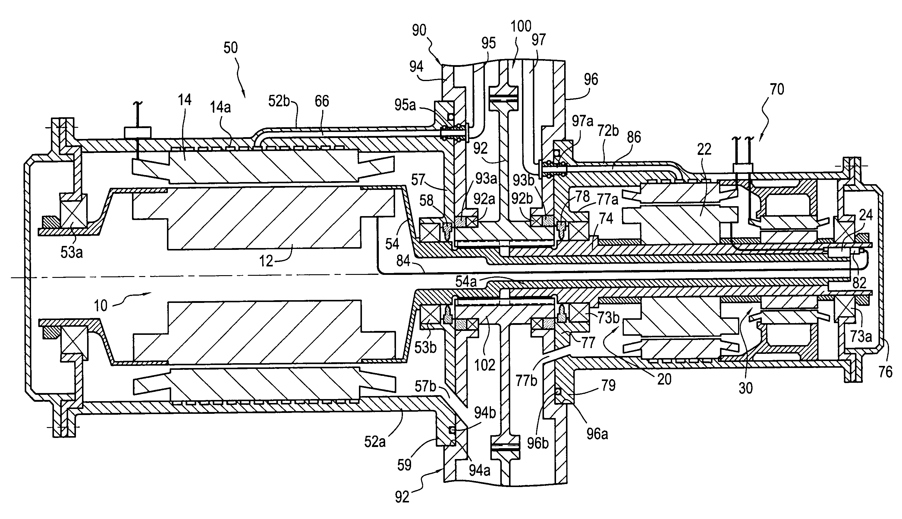
The present invention proposes an S / G architecture for a gas turbine that reduces weight and bulk while still being easy to disassemble for maintenance or repair purposes. The architecture includes a starter / generator for a gas turbine with a generator module and an exciter module, both housed separately from a gearbox. The generator module has a stator and a rotor, while the exciter module has a stator and a rotor. The two modules are connected through an electrical connection. The invention also includes a permanent magnet generator that can be housed in either the generator module or the exciter module. The weight of the generator module or the exciter module can be reduced because they have distinct mechanical coupling shafts. The electrical connection can be housed inside the shafts or outside them, and the shafts can be connected to gearwheels or separate gearwheels. The invention also provides an assembly of the S / G coupled to a gearbox. The technical effects of the invention include reducing weight and bulk of the S / G, making maintenance or repair easier, and improving overall performance of the gas turbine.

Problems solved by technology

This leads to occupying a large amount of space and to presenting a significant weight that is cantilevered out and therefore requires attachment means of sufficient strength to enable it to be mounted on the gearbox.

Method used


Image

  • Distributed architecture for a gas-turbine starter/generator
  • Distributed architecture for a gas-turbine starter/generator
  • Distributed architecture for a gas-turbine starter/generator

Examples


Embodiment Construction

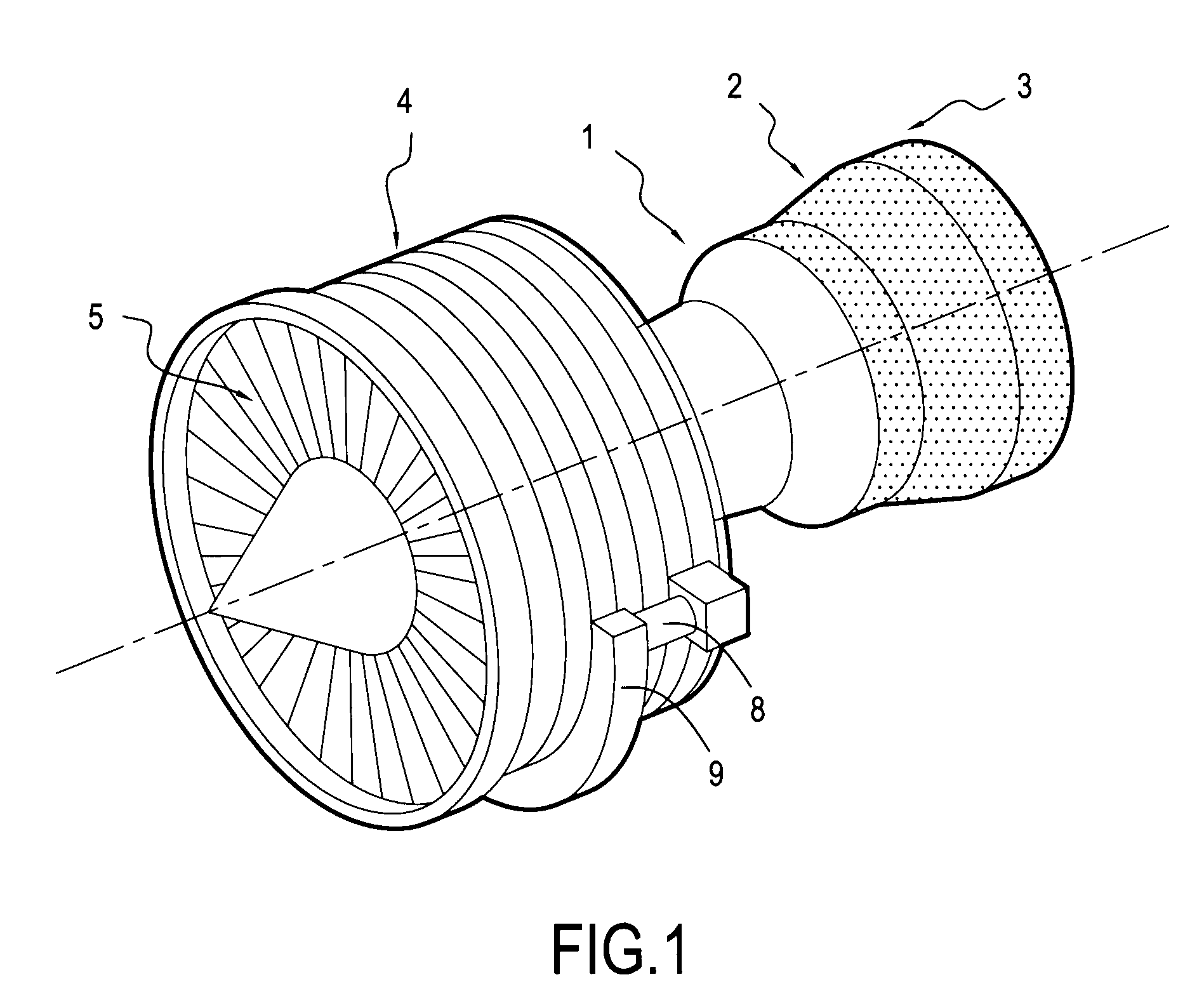
[0028]A field of application of the invention is that of gas turbine aeroengines for airplanes, of the kind shown very diagrammatically in FIG. 1, but the invention is nevertheless applicable to other gas turbine aeroengines, typically to helicopter engines, and also to auxiliary gas turbine power units.

[0029]The engine of FIG. 1 comprises a combustion chamber 1, with combustion gas from the chamber 1 driving a high pressure turbine 2 and a low pressure turbine 3. The turbine 2 is coupled by a shaft to a high pressure compressor 4 that feeds the combustion chamber 1 with air under pressure, while the turbine 3 is coupled by another shaft to a fan 5 at the inlet to the engine.

[0030]A gearbox 9 or accessory gearbox is connected via a mechanical power takeoff 8 to a turbine shaft and comprises a set of gearwheels for driving various accessories, including at least one (and generally two) starter / generators (S / Gs).

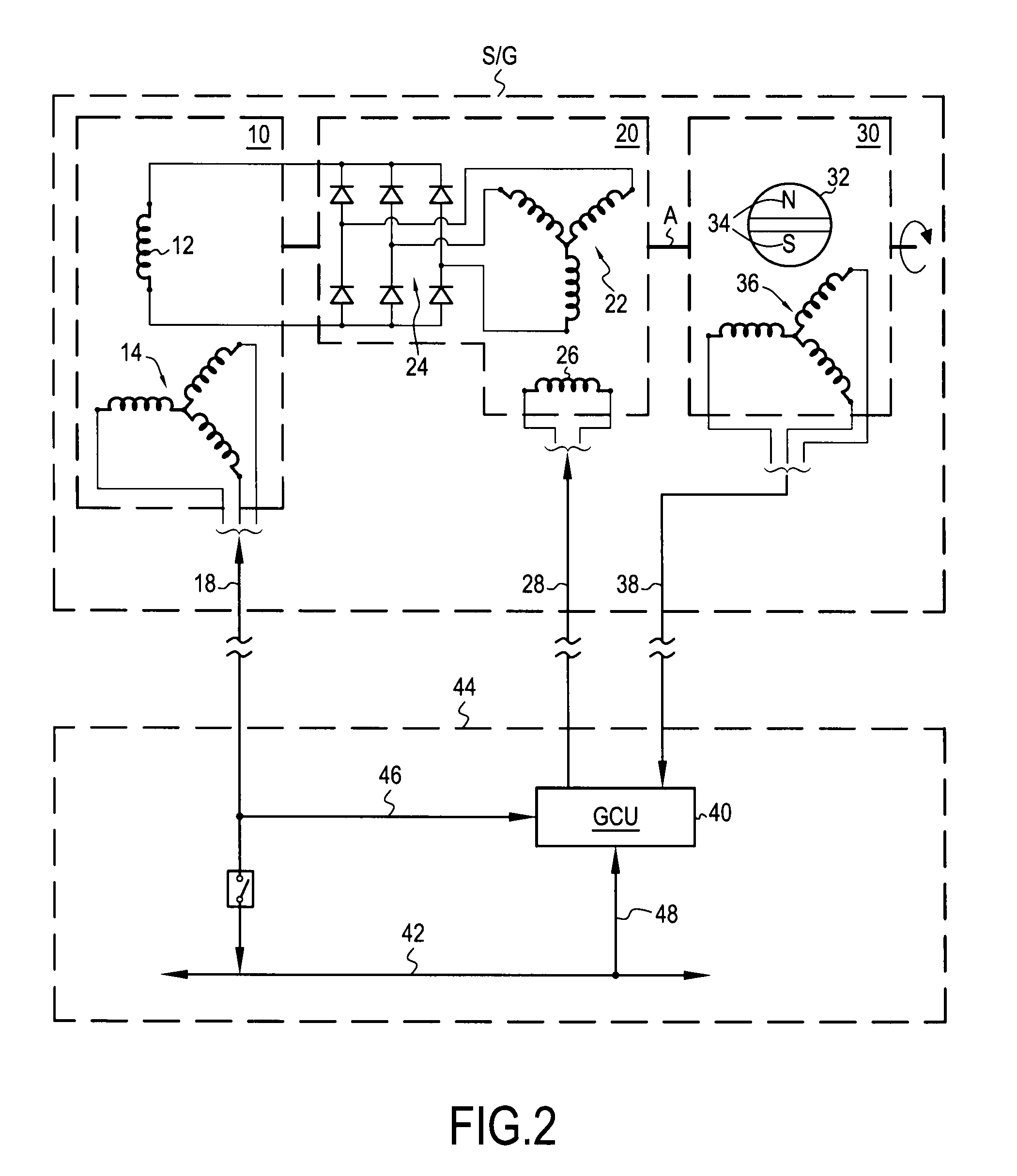
[0031]FIG. 2 is a simplified general electrical circuit diagram of S / G co...


PUM


Abstract

A gas-turbine starter / generator comprises: a generator module comprising a first casing, a generator housed in the first casing, and a first shaft constrained to rotate with the rotor of the generator, projecting from the first casing, and carrying a first mechanical coupling member; an exciter module, comprising a second casing, an exciter housed in the second casing, and a second shaft distinct from the first shaft, constrained to rotate with the rotor of the exciter, projecting from the second casing, and carrying a second mechanical coupling member; and an electrical connection comprising a rectifier and at least one connector for connecting the secondary circuit of the exciter to the primary circuit of the generator. The mechanical coupling members are coupled to a common gearwheel or to respective different gearwheels of a gearbox of the gas turbine.

Description

BACKGROUND OF THE INVENTION[0001]The invention relates to gas turbines, and more particularly to mounting a starter / generator (S / G) on a gearbox, or an accessory gearbox. The field of application of the invention is that of gas turbines for aeroengines for airplanes or helicopters, and also that of auxiliary power units (APUs).[0002]In a gas turbine, certain pieces of equipment or “accessories” are driven by a mechanical transmission using mechanical power taken from a turbine shaft. The mechanical transmission includes a set of gearwheels housed in a casing and is referred to as a gearbox or as an accessory gearbox. Accessories include in particular various pumps for producing hydraulic energy, of for delivering fuel or lubricant, and also one or more electrical S / Gs.[0003]While a gas turbine is in operation, the or each S / G acts as an electricity generator and produces electricity that powers one or more electricity distribution centers for the airplane or the helicopter and its e...

Claims


Application Information

Patent Timeline
Patent Type & Authority Applications(United States)
IPC IPC(8): H02K7/116H02K7/20
CPCH02K11/042H02K7/116H02K19/38H02K9/19
Inventor BECQUERELLE, SAMUEL RAYMOND GERMAINGALIVEL, JEAN-PIERRE
Owner SAFRAN ELECTRICAL & POWER
Learn More