
Power feed control circuit for on-vehicle electronic control apparatuses

a technology of electronic control apparatus and control circuit, which is applied in the direction of load balancing in dc network, electric devices, transportation and packaging, etc., can solve the problems of uneconomic setup and inability to perform general management of power source relays, and achieve low price and small configuration size

Inactive Publication Date: 2008-10-02
MITSUBISHI ELECTRIC CORP
View PDF6 Cites 24 Cited by
  • Summary
  • Abstract
  • Description
  • Claims
  • Application Information

AI Technical Summary

Benefits of technology

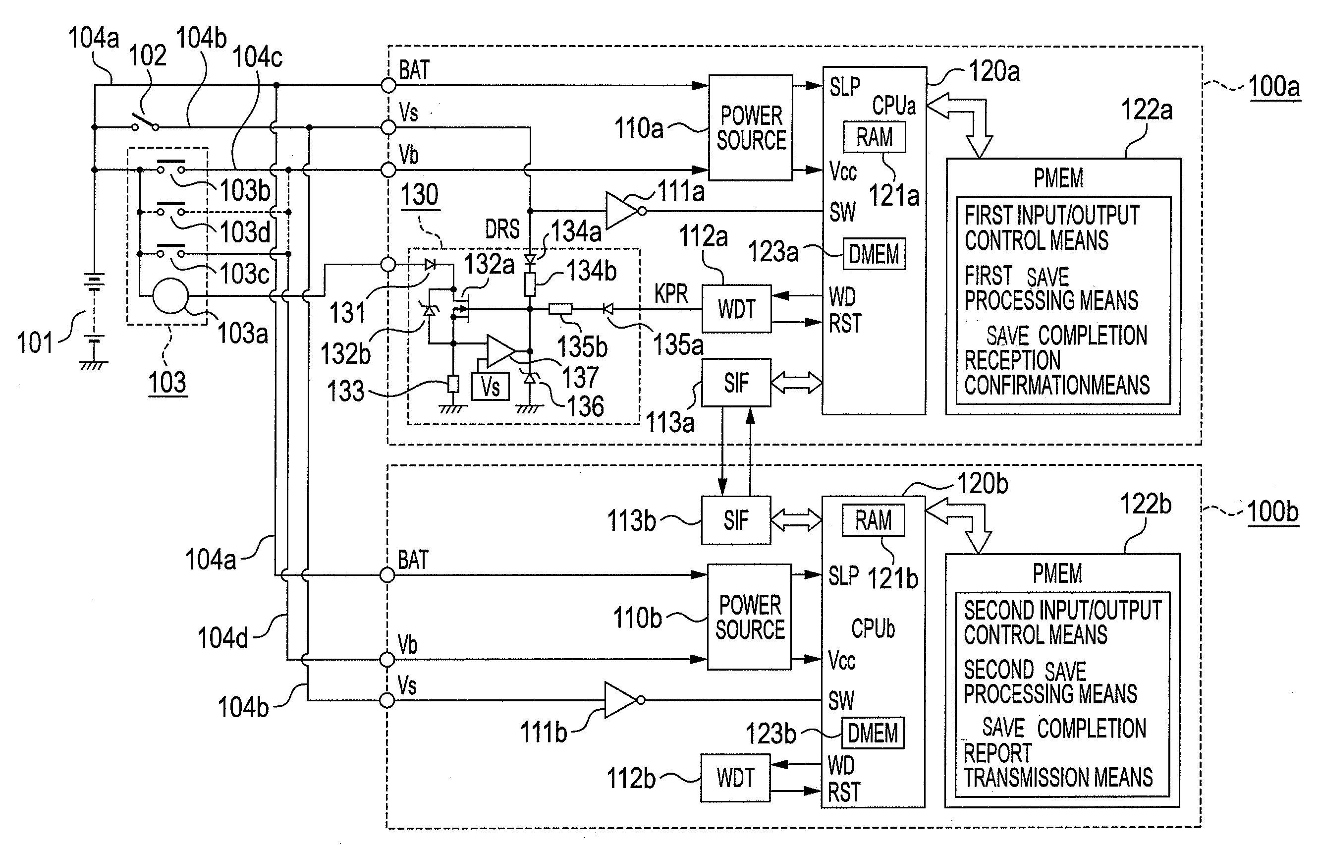
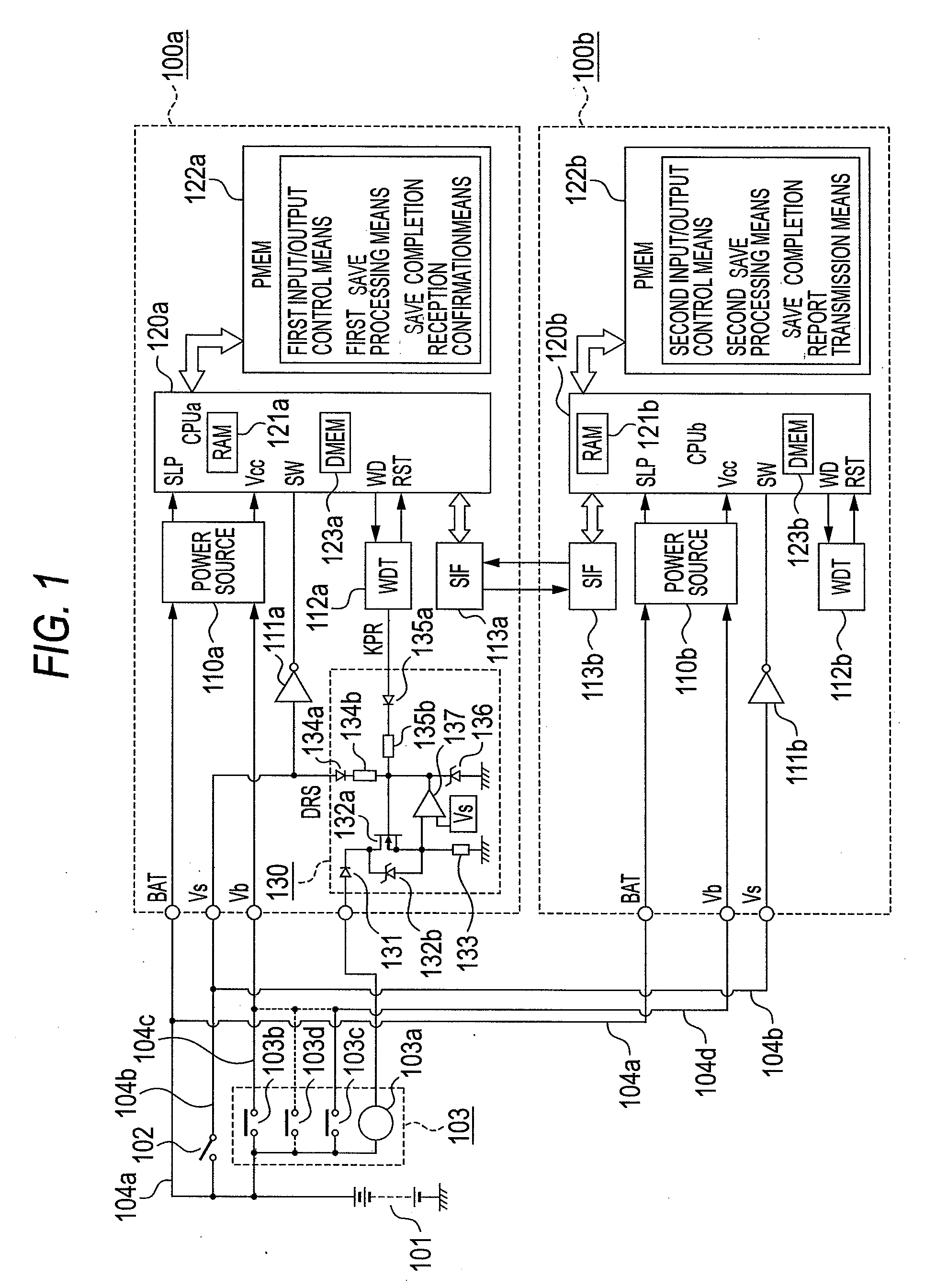
[0013]In accordance with the power feed control circuit for the on-vehicle electronic control apparatuses according to this invention, the energization control circuit of the power source relay is disposed in only the first on-vehicle electronic control apparatus. Therefore, the power feed control circuit has the advantage that the configuration becomes small in size and low in price as a whole. Another advantage is that the collaborative operations of the activations, stops and save processing steps of the first and second on-vehicle electronic control apparatuses are permitted, and that the power source can be cut off after the completions of the first and second save processing steps have been confirmed.
[0014]Besides, the first and second on-vehicle electronic control apparatuses which have the control functions independent of each other, owing to the first and second microprocessors are connected with each other through the serial communication interface circuits. Therefore, the control circuit has the advantage that the whole control functions are enhanced by the mutual supervisions of the first and second microprocessors and the exchanges of input / output information items during running.

Problems solved by technology

This poses, not only the problem that the setup is uneconomical, but also the problem that the general management of the power source relays cannot be performed.

Method used


Image

  • Power feed control circuit for on-vehicle electronic control apparatuses
  • Power feed control circuit for on-vehicle electronic control apparatuses
  • Power feed control circuit for on-vehicle electronic control apparatuses

Examples


embodiment 1

(1) Detailed Description of Configuration

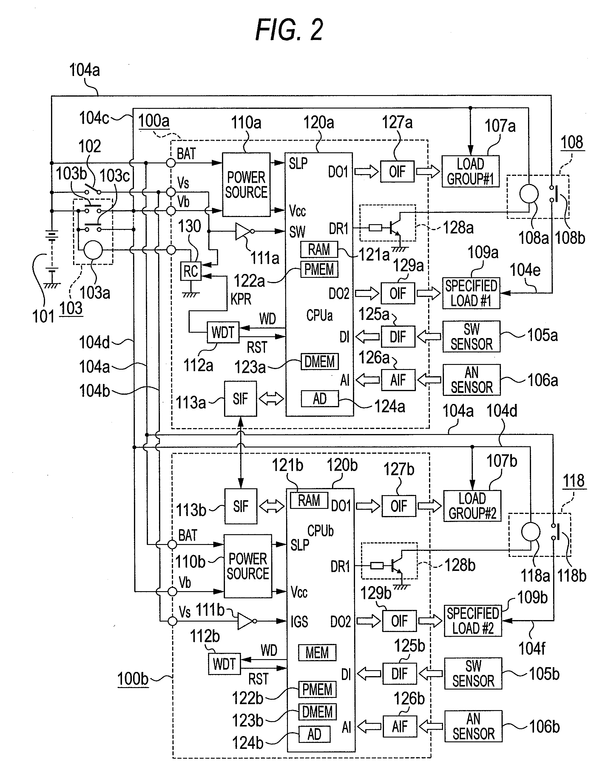
[0024]Now, the circuit configuration of the major portions of a power feed control circuit for on-vehicle electronic control apparatuses according to Embodiment 1 of this invention will be described in detail in conjunction with FIG. 1. Referring to FIG. 1, the first on-vehicle electronic control apparatus 100a operates with its principal constituent being a first microprocessor 120a to be stated later, and it is configured so as to be connected through a detachable connector not shown, with a power feed circuit which will be described below.

[0025]Likewise, the second on-vehicle electronic control apparatus 100b operates with its principal constituent being a second microprocessor 120b to be stated later, and it is configured so as to be connected through a detachable connector not shown, with a power feed circuit which will be described below. An on-vehicle battery 101 generates a DC voltage of, for example, DC 12 [V], and it is connected to...

embodiment 2

(1) Detailed Description of Configuration

[0131]Now, a power feed control circuit for on-vehicle electronic control apparatuses according to Embodiment 2 of this invention will be described in detail in conjunction with FIG. 5. FIG. 5 shows a circuit diagram of the major portions of the power feed control circuit. In the ensuing description, the points of difference from Embodiment 1 shown in FIG. 1 will be chiefly explained. Referring to FIG. 5, the first on-vehicle electronic control apparatus 200a operates with its principal constituent being a first microprocessor 220a to be stated later, and it is configured so as to be connected through a detachable connector not shown, with a power feed circuit which will be described below.

[0132]Likewise, the second on-vehicle electronic control apparatus 200b operates with its principal constituent being a second microprocessor 220b to be stated later, and it is configured so as to be connected through a detachable connector not shown, with ...


PUM


Abstract

First and second on-vehicle electronic control apparatuses which communicate with each other through serial communication interface circuits are fed with powers through an output contact of a power source relay from an on-vehicle battery, an electromagnetic coil of the power source relay is energized through a transistor when a power source switch has been closed, first and second microprocessors are activated upon closure of the output contact, a first watchdog timer generates a self-holding command signal and keeps an operating state of the power source relay when intervals of a watchdog signal which is generated by the first microprocessor are normal, and the self-holding command signal is stopped to deenergize the power source relay, when the first and second on-vehicle electronic control apparatuses have completed their save processing steps in accordance with opening of the power source switch.

Description

BACKGROUND OF THE INVENTION[0001]1. Field of the Invention[0002]This invention relates to a power feed control circuit for an on-vehicle electronic control apparatus which is fed with power through a power source relay from an on-vehicle battery. More particularly, it relates to improvements in a power feed control circuit for a plurality of on-vehicle electronic control apparatuses, for example, an engine control apparatus and a transmission control apparatus, which are relevant to each other.[0003]2. Description of the Related Art[0004]In each of various on-vehicle electronic control apparatuses such as an engine control apparatus in which an ignition control and a fuel injection control are chiefly performed, an electronic throttle control apparatus in which the valve opening degree of a suction throttle is controlled by an electric motor in response to the trodden degree of an accelerator pedal, a transmission control apparatus in which a speed change stage is variably controlle...

Claims


Application Information

Patent Timeline
IPC IPC(8): B60L1/00
CPCH02J1/14B60R16/03H02J2310/46
Inventor HASHIMOTO, KOJITSUNEKAZU, SHOSO
Owner MITSUBISHI ELECTRIC CORP
Learn More