Level-converted and clock-gated latch and sequential logic circuit having the same

Inactive Publication Date: 2008-10-02
SAMSUNG ELECTRONICS CO LTD
View PDF2 Cites 22 Cited by
  • Summary
  • Abstract
  • Description
  • Claims
  • Application Information

AI Technical Summary

Benefits of technology

[0029]Therefore, the level-converted and clock-gated latch according to exemplary embodiments of the present invention converts a clock signal swingin

Problems solved by technology

In the circuit illustrated in FIG. 1, however, when the amplitude of the gated clock signal GCK is substantially the same as the amplitude of the clock signal CK, a delay increases in the critical path of the flip-flop.
Th

Method used


Image

  • Level-converted and clock-gated latch and sequential logic circuit having the same
  • Level-converted and clock-gated latch and sequential logic circuit having the same
  • Level-converted and clock-gated latch and sequential logic circuit having the same

Examples


Embodiment Construction

[0042]Exemplary embodiments of the present invention now will be described more fully with reference to the accompanying drawings, in which exemplary embodiments of the invention are shown. The present invention may, however, be embodied in many different forms and should not be construed as limited to the exemplary embodiments set forth herein. Rather, these exemplary embodiments are provided so that this disclosure will be thorough and complete, and will fully convey the scope of the invention to those of ordinary skill in the art. Like reference numerals refer to like elements throughout this application.

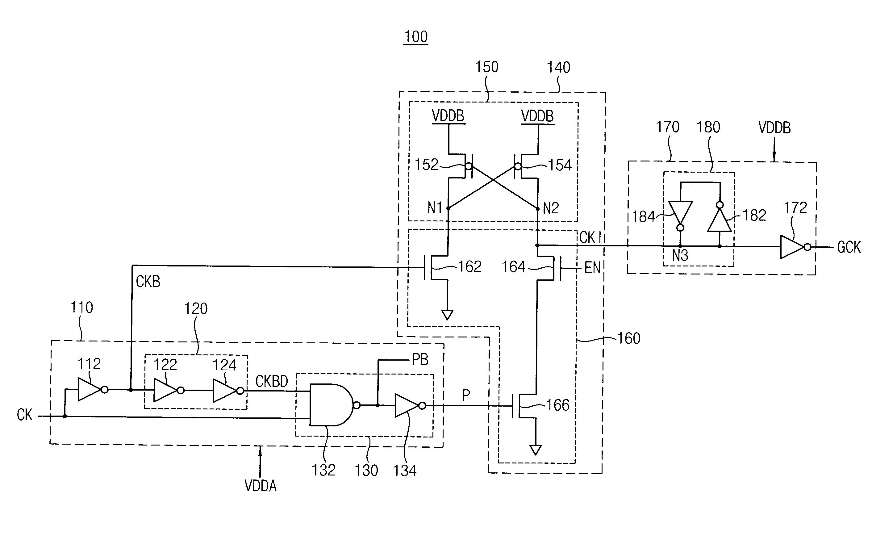
[0043]FIG. 4 is a circuit diagram illustrating a level-converted and clock-gated latch according to an exemplary embodiment of the present invention.

[0044]Referring to FIG. 4, a level-converted and clock-gated latch 100 includes a pulse generator 110, a level converting unit 140, and a latch circuit 170.

[0045]The pulse generator 110 includes a first inverter 112, a delay unit 120...


PUM


Abstract

A level-converted and clock-gated latch includes a pulse generator, a level converting unit, and a latch circuit. The pulse generator is provided with a first power-supply voltage and generates a pulse signal having a first voltage level, in response to a clock signal. The level converting unit is provided with a second power-supply voltage and generates an intermediate clock signal having a second voltage level, in response to an inverted clock signal, the clock signal and an enable signal. The latch circuit is provided with the second power-supply voltage, latches the intermediate clock signal, and provides a gated clock signal having the second voltage level. An activation interval of the gated clock signal is controlled based on the enable signal.

Description

CROSS-REFERENCE TO RELATED APPLICATION[0001]This application claims priority under 35 USC §119 to Korean Patent Application No. 2007-0032264, filed on Apr. 2, 2007 in the Korean Intellectual Property Office (KIPO), the disclosure of which is incorporated herein in its entirety by reference.BACKGROUND OF THE INVENTION[0002]1. Technical Field[0003]The present disclosure relates to a semiconductor integrated circuit and, more particularly, to a gated latch.[0004]2. Discussion of Related Art[0005]Digital logic circuits can generally be characterized as either combinational circuits or sequential circuits. Combinational circuits are based on logic gates, and outputs of the logic gates are directly determined by the present input values applied to the circuit. Combinational circuits perform operations that are logically specified by a series of Boolean expressions. Sequential circuits may also include logic gates, but additionally employ storage devices such as flip-flops. The outputs of ...

Claims


Application Information

Patent Timeline
IPC IPC(8): H03K3/356
CPCG06F1/08H03K3/356113G11C5/14G11C7/22
Inventor KIM, MIN-SU
Owner SAMSUNG ELECTRONICS CO LTD
Why Eureka
Try Eureka