System and method for varying response amplitude of radio transponders

a radio transponder and response amplitude technology, applied in the field of radio frequency identification systems, can solve the problems of raising consumer privacy concerns, killing commands, and limiting the efficiency of communication with tags

Inactive Publication Date: 2008-10-02
IBM CORP
View PDF11 Cites 23 Cited by
  • Summary
  • Abstract
  • Description
  • Claims
  • Application Information

AI Technical Summary

Benefits of technology

[0006]Systems and methods in accordance with the present invention provide for the modification and partial deactivation of an RFID tag by controlling the amplitude of the backscatter radiation that the tag uses to communicate with an RFID base station or reader. In one embodiment, the function of the chip component of an RFID tag or transponder, including the circuitry included in the chip component, is controlled to alter the tag function to inhibit the ability of a base station or reader to interrogate the RFID tag or transponder by wireless means for those tags that have been instructed by wireless means to limit the efficiency of the communications with the tag. Systems and methods in accordance with the present invention can provide for both the permanent and temporary modification, deactivation or disabling of wireless RFID tags. A typical RFID tag is a chip-based tag that includes an antenna and a chip in communication with the antenna. The chip includes circuitry and in particular front end circuitry that can modify the effective reading range of the tag in response to a command from an RFID reader.
[0007]In one embodiment of a method for controlling a radio frequency identification system in accordance with the present invention, at least one command from a radio frequency identification reader is communicated to a chip-based radio frequency identification tag that includes an antenna and a chip in communication with the antenna. The effective reading range of the radio frequency identification tag is then modified in response to the communicated command. In one embodiment, modification of the effective reading range of the tag includes adjusting the effective reading range between a maximum reading range and a minimum reading range. In one embodiment, modification of the effective reading range of the tag includes reducing a modulation depth of a backscatter signal transmitted by the radio frequency identification tag in response to an interrogation signal from the radio frequency identification reader. Reduction of the modulation depth includes modulating impedance values between the antenna and the chip between two modulation states and limiting impedance difference between the two modulation states.
[0010]In one embodiment, the interrogation signal is communicated to each one of a plurality of chip-based radio frequency identification calibration tags that each contain an antenna and a chip in communication with the antenna. Each calibration tag is located a known distance form each one of the plurality of radio frequency identification readers. A response signal is transmitted from the calibration tags tag to each one of a plurality of radio frequency identification readers, and the effective reading range of the transmitted response signals are reduced over time. The minimum effective reading range of the transmitted response signal is identified for each calibration tag and radio frequency identification reader, and the effective reading range between each calibration tag and radio frequency identification reader is associated with the known distance. These associations between effective reading ranges and distances are used to determine the location of the radio frequency identification tag. In one embodiment, the electrical characteristics of front end electronics in the chip of the radio frequency identification tag are modified in order to reduce the effective reading ranges.

Problems solved by technology

Since the tag is still active, that tag can be read after sale while the item is in the possession of the consumer, raising consumer privacy concerns.
However, there are problems associated with the kill command.
For example, if the kill command permanently disables a tag, then the tag may not be used for future applications including use of the tag for recalls or returns.

Method used


Image

  • System and method for varying response amplitude of radio transponders
  • System and method for varying response amplitude of radio transponders
  • System and method for varying response amplitude of radio transponders

Examples


Embodiment Construction

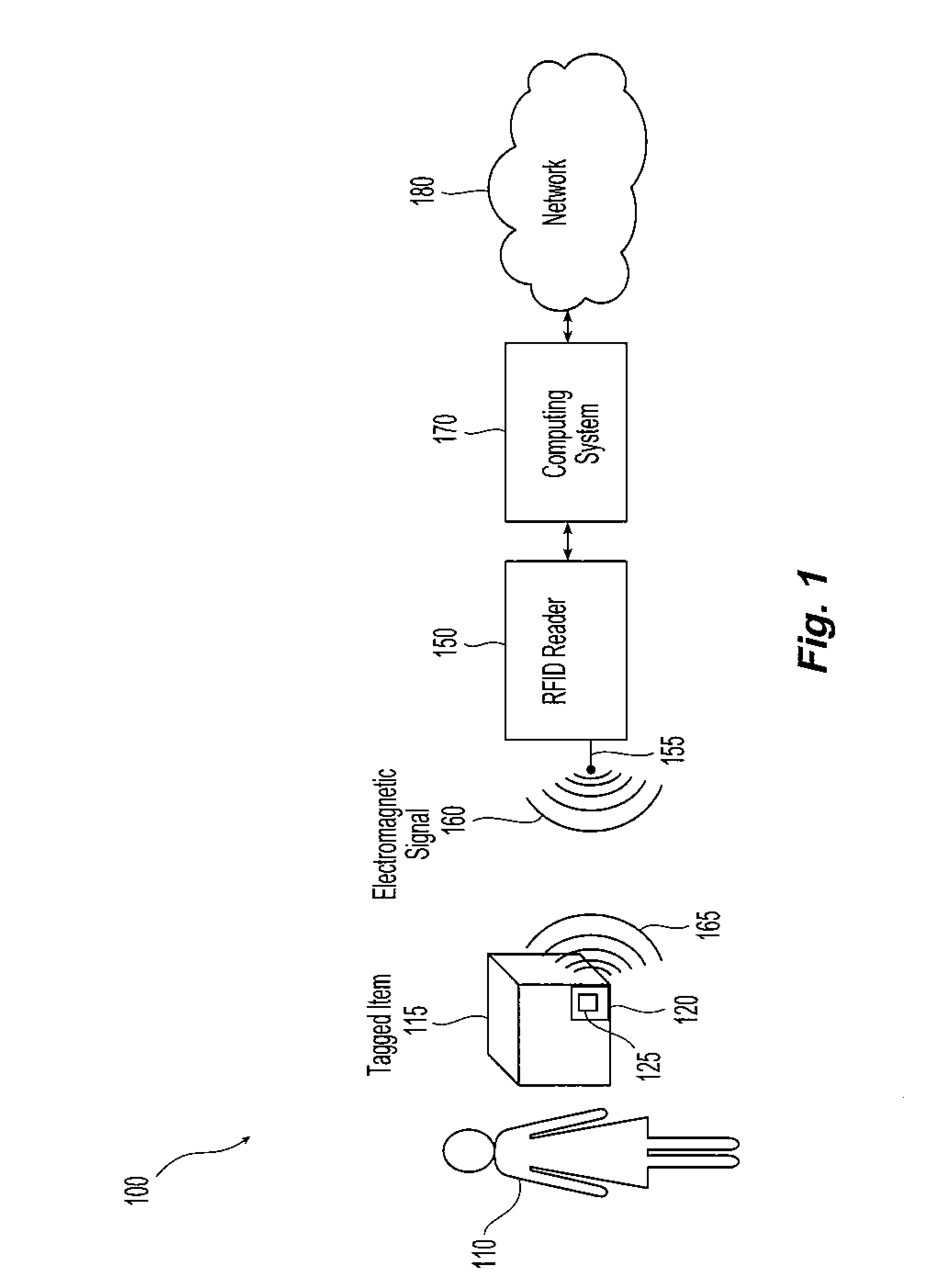
[0021]Referring initially to FIG. 1, an exemplary embodiment of a radio frequency identification (RFID) system 100 for use in accordance with the present invention is illustrated. A user 110, for example a person, customer, worker or cardholder, carries an item 115 that has at least one attached wireless or RFID tag 120. The RFID tag includes an antenna 125 and a chip (not shown) in communication with the antenna. The chip includes circuitry that enables the recovery of data and, in the case of a passive or field-powered tag, power from the signals present on the antenna as well as circuitry that enables signals to be sent from the tag to an RFID reader 150. The chip may also include additional circuitry enabling, for example, changing chip operating mode, processing of incoming data or processing of outgoing data. Thus, the chip includes diode detection, logic and memory circuits. The system also includes an RFID reader 150 that includes an antenna 155. Suitable RFID readers or bas...


PUM


Abstract

A system and method are provided for modifying the effective reading range of an radio frequency identification tag. The tag, a chip based tag, includes an antenna and a chip in communication with the antenna. The chip includes circuitry including field effect transistors that can modify the effective reading range of the tag by modifying characteristics of the tag including the modulation depth of the backscatter signal, the impedance characteristics of the tag front end electronics, the power consumption characteristics and the threshold power-on voltage of the tag. These characteristics are change either temporarily or permanently in response to commands communicated to the tag from a radio frequency identification reader.

Description

FIELD OF THE INVENTION[0001]The present invention relates to radio frequency identification systems and methods for the use of these systems.BACKGROUND OF THE INVENTION[0002]Portable transponders employing Radio Frequency Identification (RFID) are used in a variety of applications including to collect highway tolls, to provide personal identification for access control and to provide electronic information interchange, i.e. credit. Passive RFID tags, i.e., tags without internal power sources such as batteries, and wireless cards contain chips, for example computer chips, microchips and memory chips, that store data or information such as identification information, credit card numbers and financial data. These passive tags are applied to items and provide identification information in much the same way as machine-readable optical tags such as bar codes are used. The data or information stored on a tag or wireless card is retrieved using an RFID base station or reader. The reader tra...

Claims


Application Information

Patent Timeline
Patent Type & Authority Applications(United States)
IPC IPC(8): H04Q5/22
CPCG06K19/0701G06K19/0723G08B13/2417
Inventor CHEN, HANFRIEDMAN, DANIEL J.MOSKOWITZ, PAUL A.
Owner IBM CORP
Why Eureka
Try Eureka