Balanced Antenna Devices

a technology of balanced antennas and antenna devices, applied in the direction of coupling devices, waveguide type devices, resonance antennas, etc., can solve the problems of unbalanced pifas and monopoles, which cannot be used in a variety of different applications, and achieve the effect of improving bandwidth and bandwidth

Inactive Publication Date: 2008-10-02
ANTENOVA LTD +1
View PDF16 Cites 11 Cited by
  • Summary
  • Abstract
  • Description
  • Claims
  • Application Information

AI Technical Summary

Benefits of technology

[0014]Alternatively, the radiating arms of the dipole may be folded or have a meandering configuration in their respective planes. Although the radiating arms of the dipole may be coextensive, it has been found that displacing the arms with respect to each ...

Problems solved by technology

Many modern cellular radio terminals and data terminals, such as mobile telephone handsets, PDAs and laptop computers, make use of unbalanced antennas such as monopoles, planar inverted-F antennas (PIFAs), dielectric antennas, etc.
The term ‘unbalanced’ means that what appears to be the antenna is only half of the radiation mechanism, with the handset or terminal chassis acting as the other half.
It is the nature of an unbalanced antenna that it has only one input terminal, so currents in the antenna are supported by equivalent currents flowing in the groundplane Unfortunately, the groundplane in small handheld devices is small compared with the operating wavelength, sometimes as little as one half wavelength long, and in these circumstances there is a price to be paid for using the chassis as part of the antenna: if the chassis or groundpla...

Method used


Image

  • Balanced Antenna Devices
  • Balanced Antenna Devices
  • Balanced Antenna Devices

Examples


Embodiment Construction

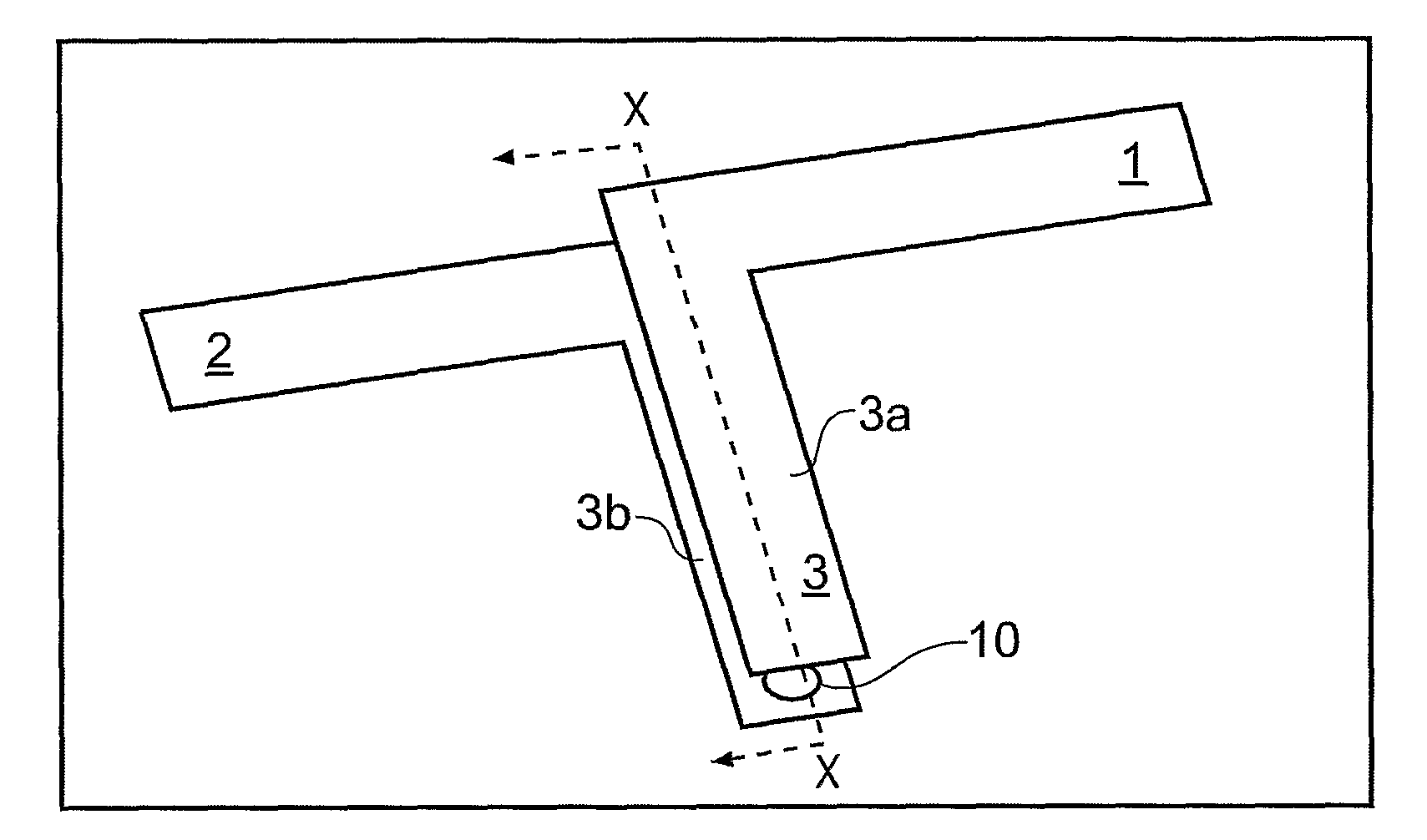
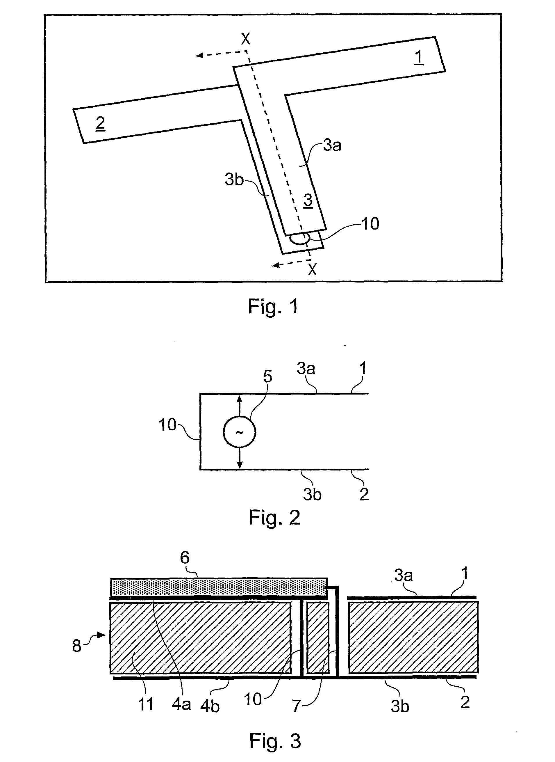
[0039]FIG. 1 shows a dipole comprising radiating arms 1, 2 connected to the ends of a parallel balanced transmission line 3 comprising two conductors 3a and 3b. A short circuit connection 10 connects both conductors and delimits the region which forms the antenna.

[0040]FIG. 2 shows a cross section XX through the arrangement of FIG. 1 where it is seen more clearly that the conductors 3a, 3b forming the parallel transmission line 3 are connected together by one or more short-circuit conductors 10. The dipole limbs cannot be physically differentiated from the transmission lines on this view (or that of FIG. 3) because they are coplanar and contiguous. The feed voltage is applied as shown by the schematic generator 5.

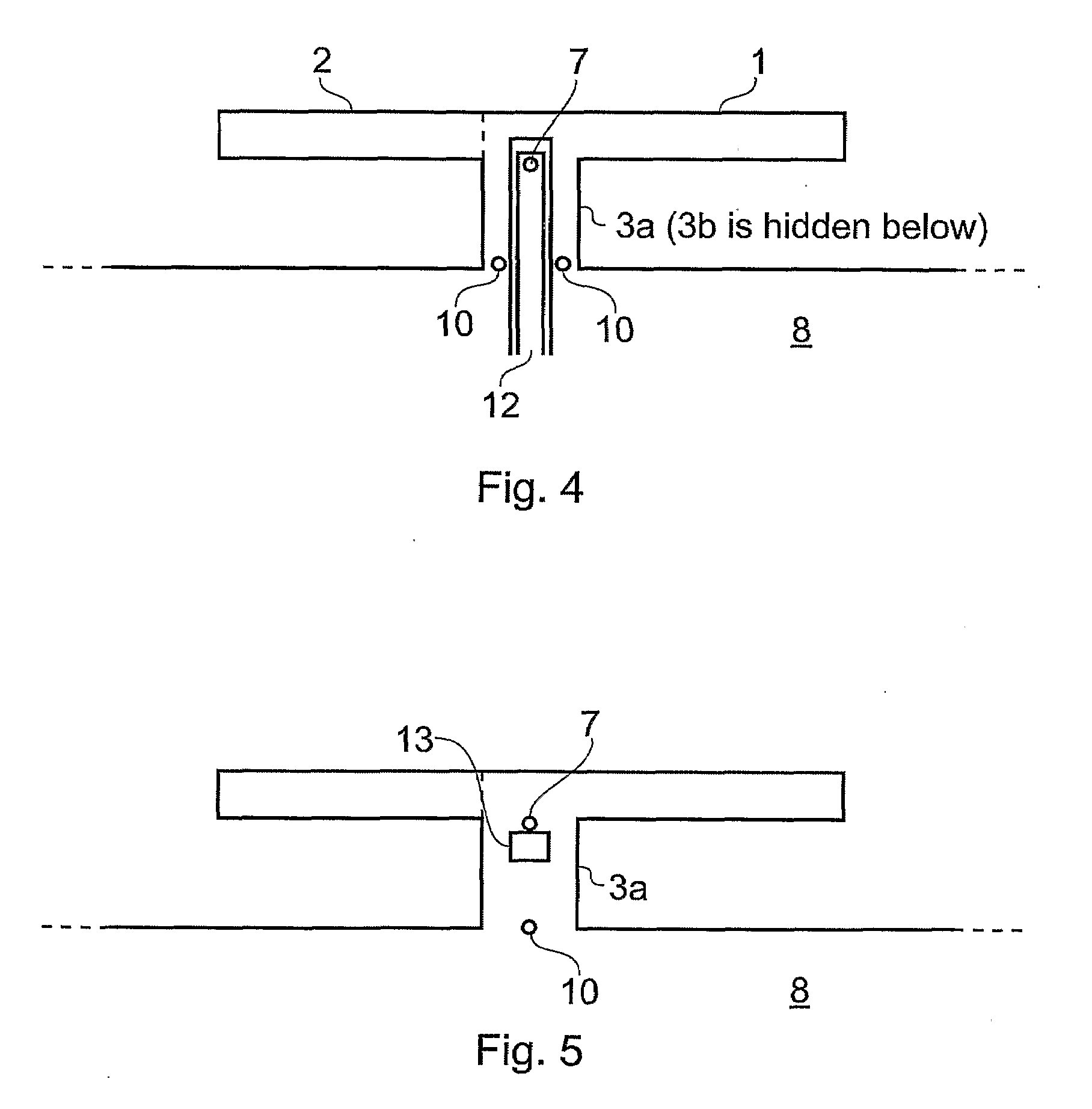
[0041]FIG. 3 shows a practical embodiment of the invention and can be related to FIG. 2 by the presence of the short-circuit 10, the transmission line 3a, 3b and the dipole limbs 1, 2. The antenna is provided with an unbalanced feed in the form of a coaxial cable with an ou...


PUM


Abstract

A balanced antenna comprising a dipole with first and second radiating arms, the radiating arms being provided with a balanced transmission line for connection to a feed, the balanced transmission line comprising first and second conductors connected to each other by a short-circuit conductor, and in which the antenna device is fed by applying a potential difference across the first and second conductors. The antenna device may be fed with an unbalanced feed, and is significantly smaller than a typical balanced dipole antenna device configured for operation at the same frequency.

Description

[0001]The present invention relates to balanced antenna devices, in particular but not exclusively for use in cellular radio terminals and data terminals.BACKGROUND[0002]Many modern cellular radio terminals and data terminals, such as mobile telephone handsets, PDAs and laptop computers, make use of unbalanced antennas such as monopoles, planar inverted-F antennas (PIFAs), dielectric antennas, etc. The term ‘unbalanced’ means that what appears to be the antenna is only half of the radiation mechanism, with the handset or terminal chassis acting as the other half. Here, chassis is a general term for the printed circuit board (PCB) together with any conductive components and assemblies connected thereto, typically including a battery, keyboard or keypad, display housings and any conductive paint applied to the casing or housing of the terminal to enhance electromagnetic compatibility (EMC) performance. The chassis and its associated conductive components form what may be regarded as t...

Claims


Application Information

Patent Timeline
IPC IPC(8): H01Q9/28H01Q1/22H01Q1/24H01Q9/26H01Q23/00
CPCH01Q1/22H01Q1/2275H01Q1/243H01Q9/26H01Q9/285H01Q23/00H01P5/10H01Q1/24H01Q1/38H01Q9/16
Inventor COLLINS, BRIAN
Owner ANTENOVA LTD
Why Eureka
Try Eureka