
Arc Flash Elimination Apparatus and Method

a technology of arc flash and apparatus, applied in the direction of emergency protective circuit arrangement, etc., can solve the problems of circuit breaker delay or no tripping, arc flash device established by regulation, and explosion of energy that destroys circuits and endangers personnel

Active Publication Date: 2008-10-02
ABB SPA
View PDF31 Cites 46 Cited by
  • Summary
  • Abstract
  • Description
  • Claims
  • Application Information

AI Technical Summary

Benefits of technology

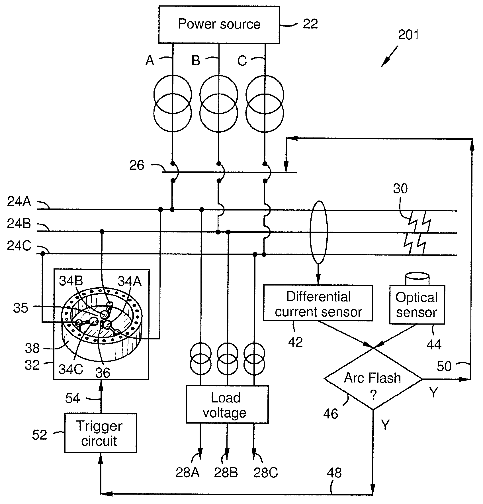
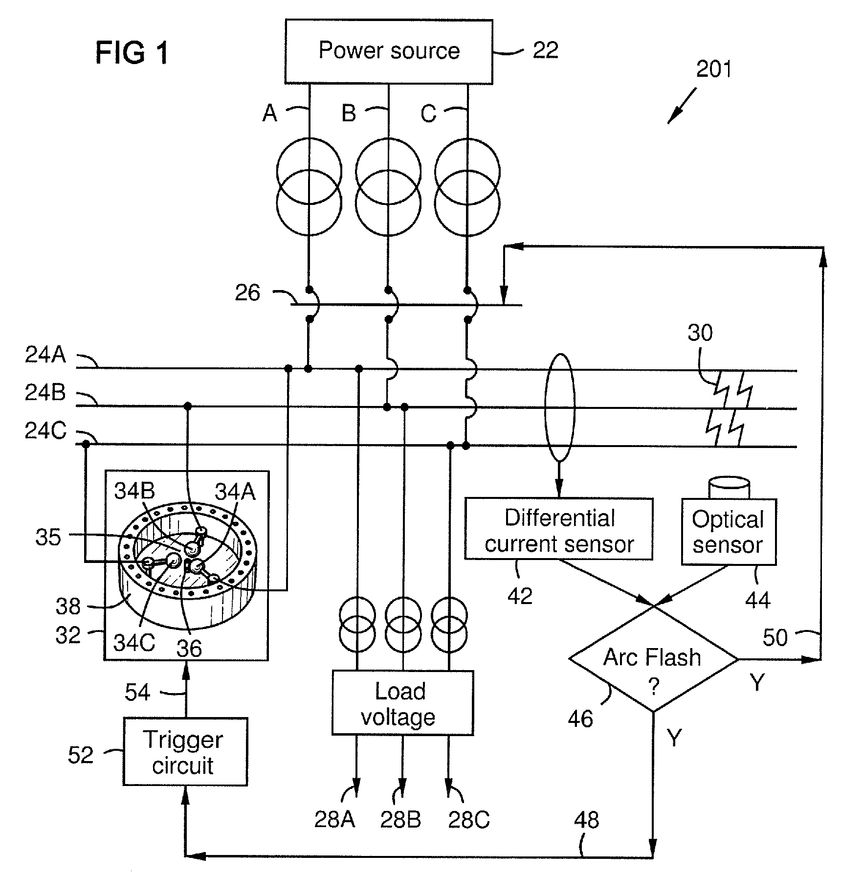
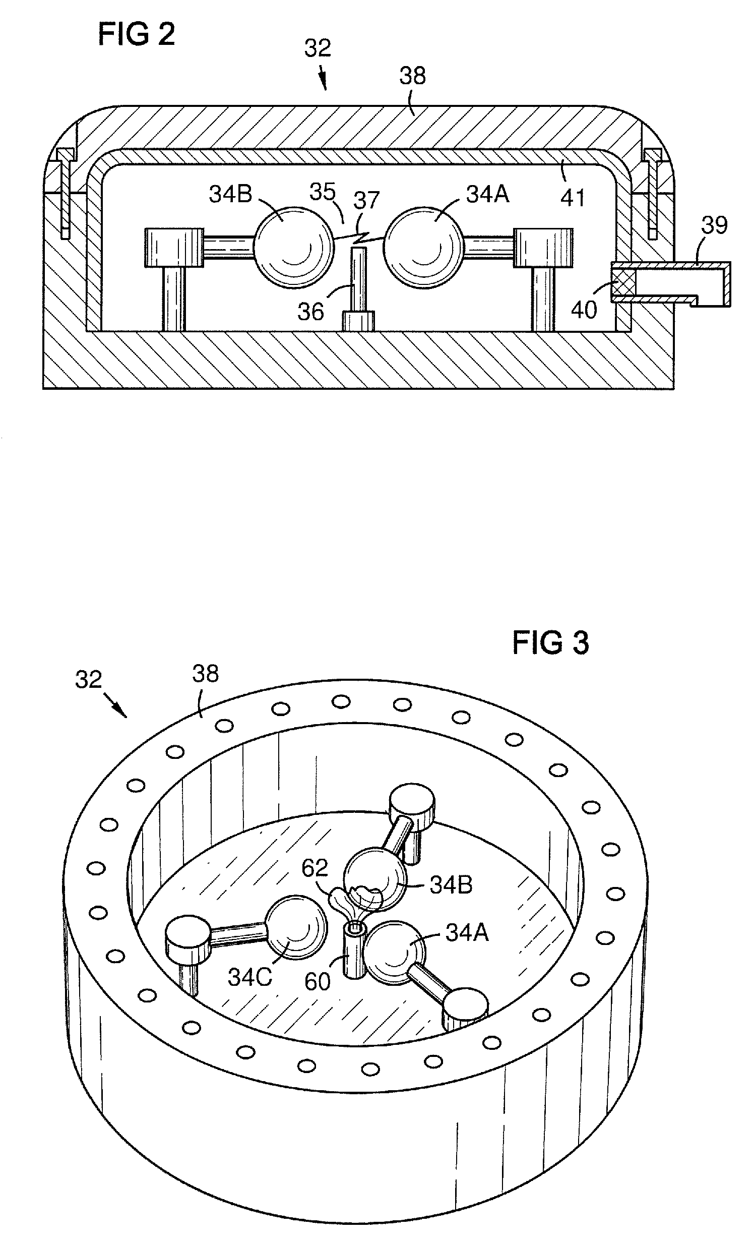
[0008]Another aspect of the invention resides in an ablative plasma gun provided as an arc crowbar triggering device that injects a plasma of ablated material into the gap between the electrodes of the arc crowbar to initiate protective arcing and lower the gap impedance for fast and effective arc flash elimination and breaker tripping.

Problems solved by technology

Arc temperature can reach as high as 20,000° C., vaporizing conductors and adjacent materials, and releasing an explosive energy that destroys circuits and endangers personnel, even at a distance.
However, the arc fault current is usually much less than a short circuit current, and hence delayed or no tripping of circuit breakers is expected unless the breakers are selected to handle an arc fault condition.
Agencies and standards such as the National Environmental Policy Act (NEPA), Occupational Safety and Health Administration (OSHA), and Institute of Electrical and Electronics Engineers (IEEE) regulate arc flash issues through personal protective clothing and equipment, but there is no device established by regulation to eliminate arc flash.
Present arc flash mitigation technologies are not satisfactory.
Standard fuses and circuit breakers do not react fast enough to an arc flash.
However, circuit breakers that rely on mechanical and / or electromechanical processes may be too slow to stop an arc flash before damage occurs.

Method used


Image

  • Arc Flash Elimination Apparatus and Method
  • Arc Flash Elimination Apparatus and Method
  • Arc Flash Elimination Apparatus and Method

Examples


Embodiment Construction

[0017]The inventors of the present invention have innovatively recognized that a controlled arc can act as an electrical crowbar for arc flash elimination, and that such a controlled arc can be faster than existing crowbars, providing better protection for circuits and personnel. FIG. 1 shows an electrical circuit 201 with a power source 22, providing 3-phase electrical power A, B, C to three respective buses 24A, 24B, 24C protected by a signal controllable circuit breaker 26. Power is provided via the buses to one or more loads 28A, 28B, 28C.

[0018]The circuit breaker 26 will open in case of a short circuit. However, it may not open in case of an arc flash 30 because the current flowing across an arc flash is lower than the bolting current of a short circuit which trips a circuit breaker. Furthermore, a mechanical breaker is too slow to prevent damage and hazard from an arc flash.

[0019]To solve this problem, an arc crowbar 32 is connected in the circuit to quickly eliminate an arc f...


PUM


Abstract

An arc crowbar with electrodes separated by a gap in a protective case. Each electrode is connected to an electrically different conductor of a circuit. A sensor detects an arc flash condition on the circuit and signals a trigger circuit to send an electrical pulse to an arc-triggering device in the arc crowbar gap. The triggering device ionizes a portion of the gas between the electrodes, initiating a protective arc between the electrodes that absorbs energy from the power circuit and trips a breaker, eliminating the arc flash condition. The triggering device may be a plasma gun, especially one that injects plasma of an ablated material into the gap. The sensor may signal a circuit breaker to open in the power circuit. Arc flash sensor types may include a differential current sensor and / or an optical sensor.

Description

BACKGROUND[0001]The present invention relates to arc flash prevention and mitigation technologies, and particularly relates to electrical crowbar devices for this purpose.[0002]Electric power circuits and switchgear have conductors separated by insulation. Air space often serves as part or all of this insulation in some areas. If the conductors are too close to each other or voltage exceeds the insulation properties, an arc can occur between conductors. Air or any insulation (gas or solid dielectrics) between conductors can become ionized, making it conductive, which enables arcing. Arc temperature can reach as high as 20,000° C., vaporizing conductors and adjacent materials, and releasing an explosive energy that destroys circuits and endangers personnel, even at a distance. For example, an arc of 10 kA / 480V has the energy of about 8 dynamite sticks. Approximately five to ten serious arc flash incidents occur in the United States daily.[0003]Arc flash is the result of a rapid energ...

Claims


Application Information

Patent Timeline
IPC IPC(8): H02H9/04
CPCH01T2/02H02H9/06H02H1/0023H01H9/30H01H33/00
Inventor ASOKAN, THANGAVELUBOPPARAJU, GOPICHANDBOHORI, ADNAN KUTUBUDDIN
Owner ABB SPA
Learn More