

Ultra high numerical aperture optical fibers
- Summary
- Abstract
- Description
- Claims
- Application Information
AI Technical Summary
Benefits of technology
Problems solved by technology
Method used
Image

Examples
Embodiment Construction
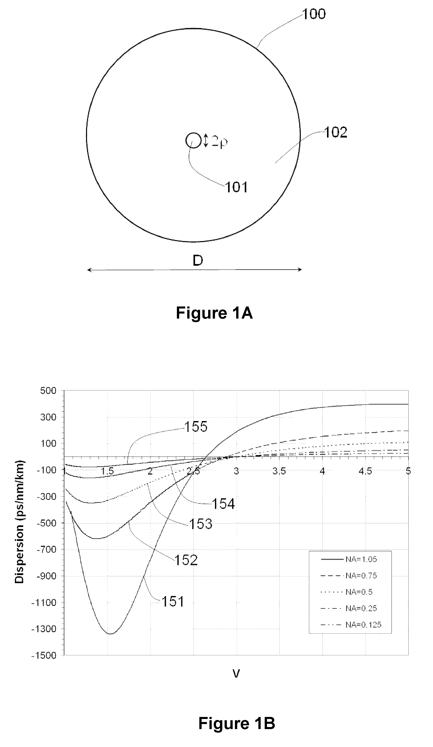
[0011]Various embodiments described herein include optical fiber designs and fabrication processes for fibers that have a higher numerical aperture and a small core size such that dispersion is pronounced. This dispersion may, for example, be two or three orders of magnitude larger than material dispersion in some embodiments.
[0012]The numerical aperture can be determined by the refractive index of the core and cladding materials. Various embodiments described herein include designs that provide high numerical index suitable for also yielding high dispersion.
[0013]In some embodiments, high dispersion can be provided at relatively small V values. In various embodiments, high numerical aperture produces increased waveguiding that enables operation at small V values with sufficiently strong waveguiding to yield low transmission loss. As described herein, the desired dispersion characteristics may also result.
[0014]In various embodiments, high numerical aperture also enables low loss si...
PUM
| Property | Measurement | Unit |
|---|---|---|
| Diameter | aaaaa | aaaaa |
| Optical gain | aaaaa | aaaaa |
| Optical gain | aaaaa | aaaaa |
Abstract
Description
Claims
Application Information