Actuator, shutter driving device for camera and method of manufacturing actuator

a technology of shutter driving device and actuator, which is applied in the direction of magnetic circuit rotating parts, instruments, magnetic circuit shape/form/construction, etc., can solve the problems of displacement between the rotor and the outputting member, the possibility of the above problem may increase, and the difficulty of maintaining the accuracy of the angular position of the outputting member against the rotor, etc., to achieve the effect of increasing the shutter speed and preventing the failur

Inactive Publication Date: 2008-10-02
SEIKO PRECISION CO LTD
View PDF6 Cites 13 Cited by
  • Summary
  • Abstract
  • Description
  • Claims
  • Application Information

AI Technical Summary

Benefits of technology

[0008]It is therefore an object of the present invention to provide an actuator, a shutter driving device for a camera, and a method of manufacturing an actuator such that the jointing of a rotor and an outputting member is strengthen.
[0009]According to an aspect of the present invention, there is provided an actuator including: a coil for excitation; a stator excited with different magnetic poles by energization of the coil; a rotor magnetized with different magnetic poles in a circumferential direction, and rotated by magnetic force generating between the rotor and the stator; and an outputting member rotated in conjunction with the rotor and outputting rotational movement of the rotor to a member, the outputting member fitting onto the rotor, the rotor having at least one of a recess portion and a projection portion at a fitting surface of the rotor, and the outputting member being jointed with the rotor so as to be shaped to the at least one of the recess portion and the projection portion by welding. These arrangements prevent the displacement of the outputting member against the rotor after welding, and strengthen the joint of the rotor and the outputting member.
[0010]According to another aspect of the present invention, there is provided a shutter driving device for a camera including: a plate having an aperture; a shutter blade for opening and closing the aperture, and an actuator for driving the shutter blade, wherein the actuator including: a coil for excitation; a stator excited with different magnetic poles by energization of the coil; a rotor magnetized with different magnetic poles in a circumferential direction, and rotated by magnetic force generating between the rotor and the stator; and an outputting member rotated in conjunction with the rotor and outputting rotational movement of the rotor to a member, the outputting member fitting onto the rotor, the rotor having at least one of a recess portion and a projection portion at a fitting surface of the rotor, and the outputting member being jointed with the rotor so as to be shaped to the at least one of the recess portion and the projection portion by welding. The shutter driving device for camera employs the actuator in which the displacement of the rotor and the outputting member is prevented, thereby dealing with the increased shutter speed, and preventing the failure by the long term use.
[0011]According to yet another aspect of the present invention, there is provided a method of manufacturing an actuator having: a rotor magnetized with different magnetic poles in a circumferential direction; and an outputting member jointed with the rotor, rotated in conjunction with the rotor, and outputting a rotational movement of the rotor to a member, the method of manufacturing the actuator including: forming at least one of a recess portion and a projection portion on a fitting surface of the rotor for fitting into the outputting member; fitting the outputting member onto the rotor, and welding the outputting member with the rotor so that the outputting member is deformed to be shaped to the at least one of a recess portion and a projection portion. These configurations strengthen the jointing of the rotor and the outputting member.

Problems solved by technology

However, in the case where the rotor and the outputting member are insert-molded, it is difficult to maintain the accuracy of the angular position of the outputting member against the rotor.
However, even if the welding joint is performed, a long-time use may weaken the joint of the rotor and the outputting member, which may cause a displacement between the rotor and the outputting member.
Specifically, as the load applied to the rotor and the outputting member increases in accordance with the faster shutter speed, the possibility of the above problem may increase.

Method used


Image

  • Actuator, shutter driving device for camera and method of manufacturing actuator
  • Actuator, shutter driving device for camera and method of manufacturing actuator
  • Actuator, shutter driving device for camera and method of manufacturing actuator

Examples


first embodiment

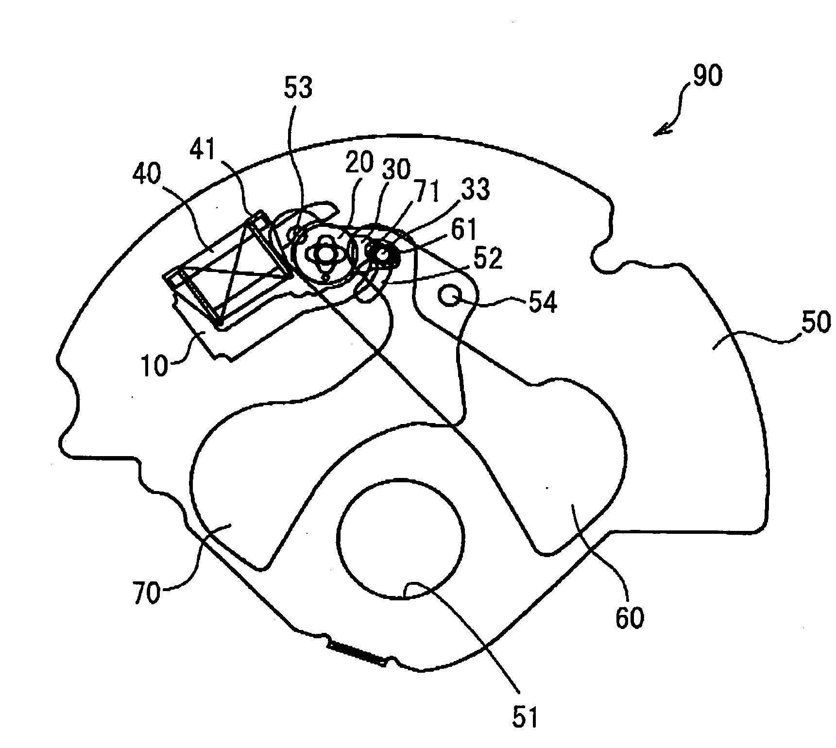
[0022]FIG. 1 is a view illustrative of an essential part of an electromagnetic actuator in accordance with a first embodiment.

[0023]An electromagnetic actuator 1 includes a stator 10, a rotor 20, an outputting member 30, and a coil 40. The stator 10 has a U shape, and has a first magnetic pole portion 11 and a second magnetic pole portion 12 at respective ends thereof. The rotor 20 has a cylindrical shape, and two different poles magnetized in the circumferential direction. The coil 40 is wound around a coil bobbin 41. The coil 40 is energized to excite the first magnetic pole portion 11 and the second magnetic pole portion 12 so as to have opposite polarities. The outputting member 30 outputting rotational movement of the rotor 20 is attached to an object side of the rotor 20 (refer to FIG. 4). Therefore, the outputting member 30 swings in conjunction with the rotor 20 within a predetermined rotational range.

[0024]The rotor 20 is made of a sintered magnet. Specifically, the rotor 2...

second embodiment

[0041]An electromagnetic actuator in accordance with a second embodiment will be described below. The same portions as those in the first embodiment are given the same reference numerals, and a description thereof will be omitted. FIG. 8 is a front view of a rotor and an outputting member employed in the electromagnetic actuator in accordance with the second embodiment.

[0042]A rotor 20d is made of magnetic resin, that is, plastic magnet. Specifically, the rotor 20d is formed of a mixture of magnetic powder of SmFeN and polyamide resin. Additionally, any material other than that mentioned above may be used for the rotor 20d. For example, NdFeB may be employed as magnetic powders, and thermoplastic polyphenylene sulfide resin or polyester polybutylene terephtalate resin may be employed as binder resin.

[0043]The rotor 20d is magnetized with the north pole and the south pole. Blind holes 23d are formed to interpose the boundary of the magnetic poles. Like the rotor 20 described in the f...


PUM

PropertyMeasurementUnit
timeaaaaaaaaaa
magneticaaaaaaaaaa
magnetic forceaaaaaaaaaa

Abstract

An actuator includes: a coil for excitation; a stator excited with different magnetic poles by energization of the coil; a rotor magnetized with different magnetic poles in a circumferential direction, and rotated by magnetic force generating between the rotor and the stator; and an outputting member rotated in conjunction with the rotor and outputting rotational movement of the rotor to a member. The outputting member fits onto the rotor, and the rotor has at least one of a recess portion and a projection portion at a fitting surface of the rotor. The outputting member is jointed with the rotor so as to have a shape corresponding to the at least one of the recess portion and the projection portion by welding.

Description

BACKGROUND OF THE INVENTION[0001]1. Field of the Invention[0002]The present invention relates to an actuator, a shutter driving device for a camera, and a method of manufacturing an actuator.[0003]2. Description of the Related Art[0004]Conventionally, there has been known an actuator used for driving a shutter blade employed in a camera, and composed of a rotor, a stator, a coil for exerting the stator, and an outputting member for transmitting the rotational movement of the rotor to the shutter blade. Japanese Patent Application Publication No 2004-191750 discloses that the rotor and the outputting member are insert-molded.[0005]However, in the case where the rotor and the outputting member are insert-molded, it is difficult to maintain the accuracy of the angular position of the outputting member against the rotor.[0006]Consequently, when the rotor and the outputting member are jointed by welding, the angular position of the outputting member against the rotor can be finely adjust...

Claims


Application Information

Patent Timeline
Patent Type & Authority Applications(United States)
IPC IPC(8): G03B9/10H02K7/14H02K15/02
CPCG03B9/10H02K1/30Y10T29/49012H02K15/03H02K37/16H02K7/14
Inventor YASUDA, AKIRAITO, AKIHIROTANAKA, MASATO
Owner SEIKO PRECISION CO LTD
Why Eureka
Try Eureka