Optical communication system, optical communication apparatus, and method of monitoring fault alarm in path section detour

a communication system and optical communication technology, applied in the field of optical communication systems and optical communication apparatuses, can solve the problems of low endurance, difficulty in applying fault avoidance for each link, and increased cos

Active Publication Date: 2008-10-02
NEC CORP
View PDF12 Cites 26 Cited by
  • Summary
  • Abstract
  • Description
  • Claims
  • Application Information

AI Technical Summary

Benefits of technology

[0021]The present invention makes it possible to avoid a fault in an appropriate section including a faulty location without performing an erroneous operation in the other sections at the time that a fault has occurred in the optical path in which a plurality of detour sections, in the all-optical communi...

Problems solved by technology

However, in the all-optical communication system, it is difficult to apply a fault avoidance being made for each link because the optical signal of the optical path is not converted to an electrical signal WDM transfer link by WDM transfer link in the transit optical communication apparatus.
For this, the longer a route length of the path becomes, the more excessively the stand-by route has to be secured, which gives rise to the problem that the cost is raised.
In ad...

Method used


Image

  • Optical communication system, optical communication apparatus, and method of monitoring fault alarm in path section detour
  • Optical communication system, optical communication apparatus, and method of monitoring fault alarm in path section detour
  • Optical communication system, optical communication apparatus, and method of monitoring fault alarm in path section detour

Examples


Embodiment Construction

[0033]Next, the best mode for carrying out the invention will be explained in details by making a reference to the accompanied drawings.

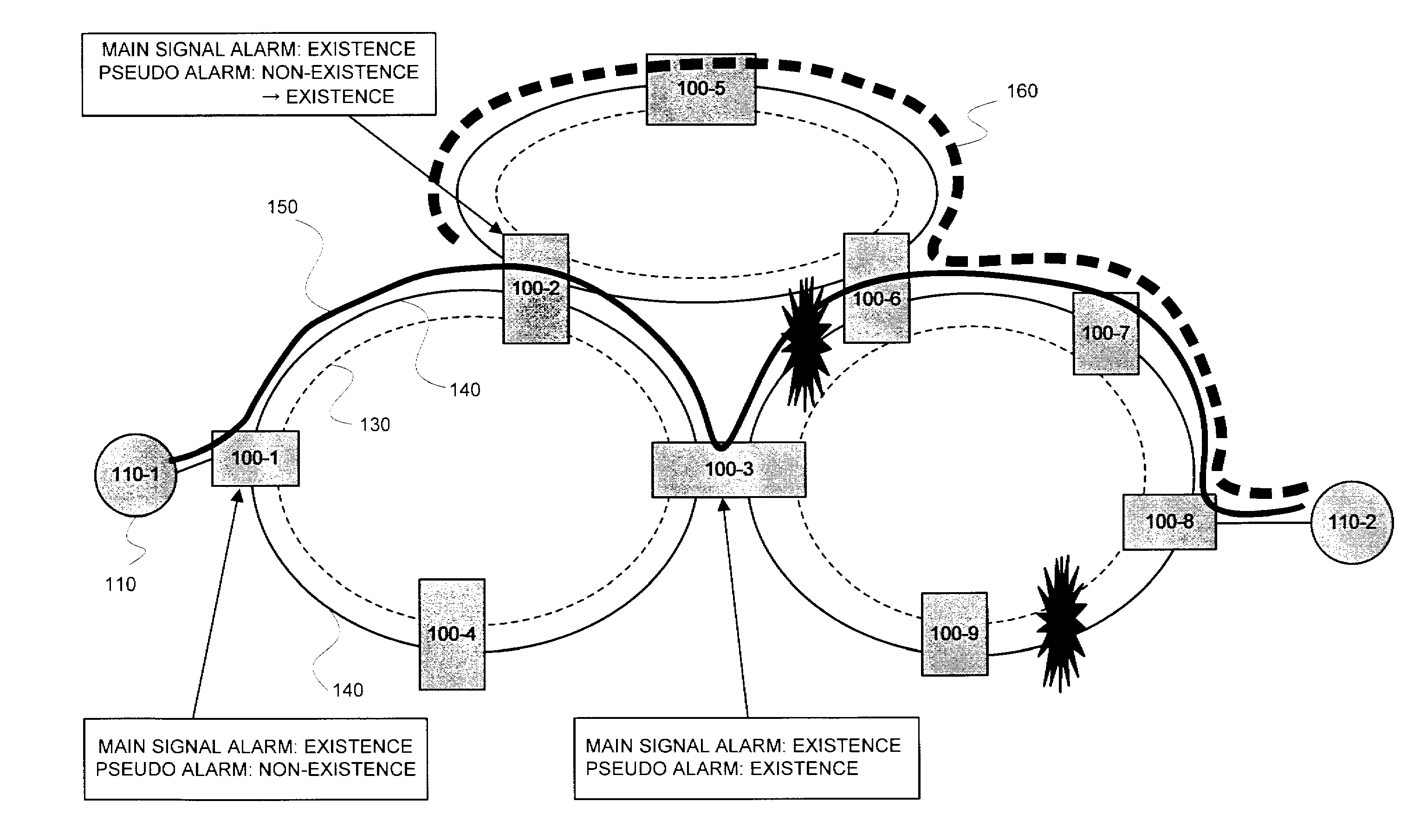
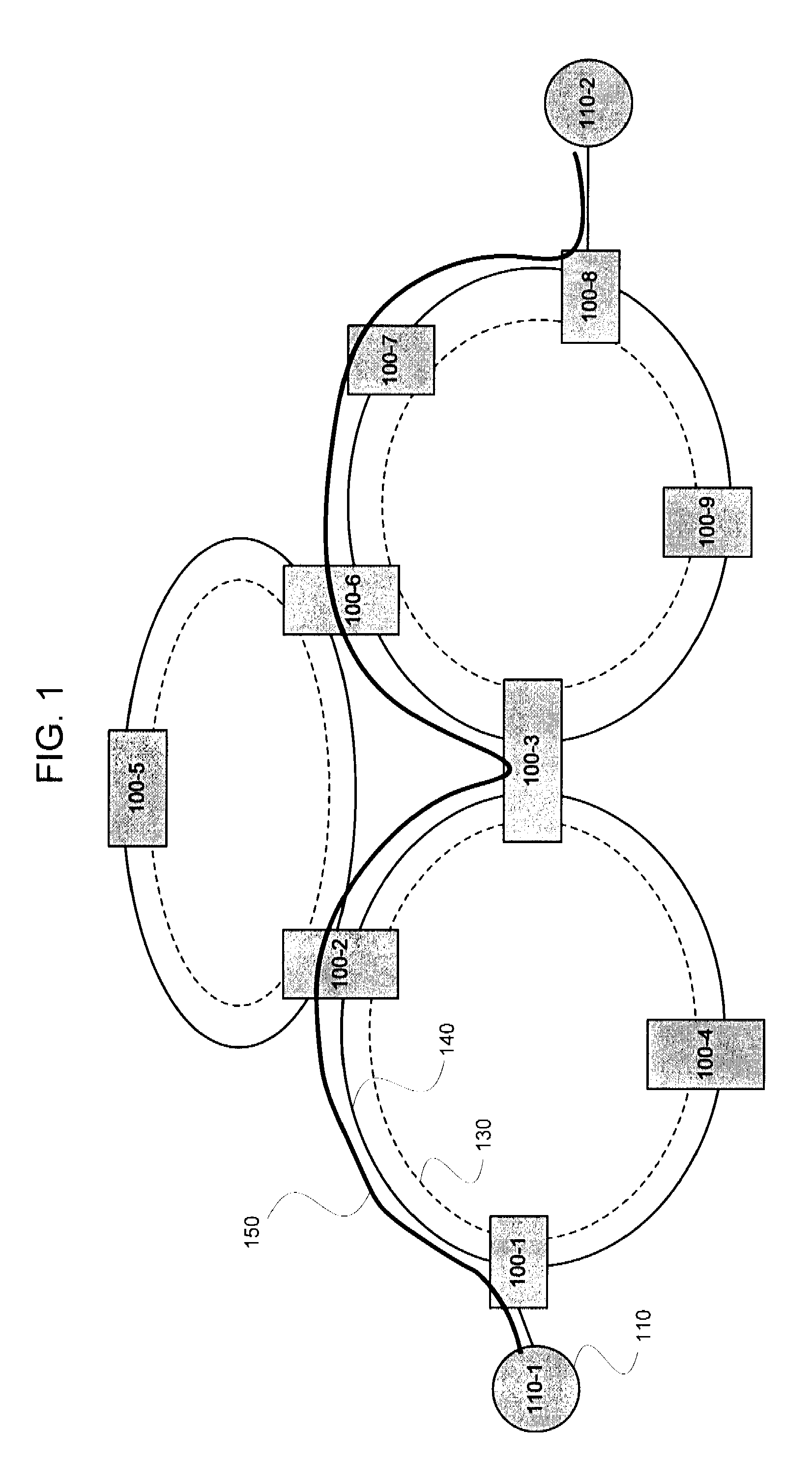
[0034]In FIG. 1, an example of a network configuration in an all-optical communication system in an exemplary embodiment of the present invention is shown. The network is comprises of a plurality of optical communication apparatuses 100-1 to 100-9 for switching an optical signal and a plurality of client apparatuses 110-1 and 110-2 (only two client apparatuses are shown in the figure, and the other client apparatuses are not shown in the figure), and the neighboring optical communication apparatuses 100 are connected to each other by employing a control channel 130 and a WDM (Wavelength Division Multiplexing) transfer link 140 that is configured of wavelength-division-multiplexed optical fibers.

[0035]The optical communication apparatus 100 and the client apparatus 110 are connected via an optical fiber having a single wavelength. Herein, the control...


PUM


Abstract

The optical communication system of the present invention is constructed with a data plane and a control plane, and includes a first monitor for monitoring a path alarm on the data plane, a second monitor for monitoring a path alarm on the control plane, and an alarm comparator for comparing alarm statuses of the optical paths that the first monitor and the second monitor preserve, wherein an optical communication apparatus, of which the first monitor and the second monitor both are in a status of having detected the alarm, operate so as to start an operation of avoiding a fault. Such a configuration makes it possible to make a detour only around an appropriate section including a fault location without performing an erroneous operation when a fault has occurred in an optical path, in which a plurality of detour sections, in an all-optical communication system.

Description

INCORPORATION BY REFERENCE[0001]This application is based upon and claims the benefit of priority from Japanese patent application No. 2007-082200, filed on Mar. 27, 2007, the disclosure of which is incorporated herein in its entirety by reference.RELATED ART[0002]The present invention relates to an optical communication system, an optical communication apparatus, and a method of making a detour around a faulty section of an optical path, and more particularly to an all-optical communication system for switching a path with an optical signal kept as it stands in a multi-ring type topology or a mesh type topology, which enables a detour for each section by dividing an optical path into a plurality of sections, and making a detour only around the corresponding section when a fault is detected, an optical communication apparatus thereof, and a method of monitoring a default alarm in a method of making a detour around a path section, being a faulty section.[0003]In the conventional opti...

Claims


Application Information

Patent Timeline
IPC IPC(8): H01S3/00H04B10/08H04B10/03H04B10/032H04B10/07H04B10/077H04L12/437
CPCH04B10/03H04B10/0773H04J14/0283H04J14/0284H04J14/0286H04J14/0291
Inventor NISHIOKA, ITARU
Owner NEC CORP
Why Eureka
Try Eureka