Emission Control System

a technology of emission control and emission control, applied in the direction of machine/engine, process and machine control, dissolving, etc., can solve the problems of insoluble elemental mercury in flue gas, inability to oxidize, inconsistent desulfurization units of flue gas, etc., to reduce sox, nox, and/or other emissions, and reduce mercury emissions.

Inactive Publication Date: 2008-10-02
NASA
View PDF32 Cites 30 Cited by
  • Summary
  • Abstract
  • Description
  • Claims
  • Application Information

AI Technical Summary

Benefits of technology

[0006]Methods and apparatus utilizing gaseous chlorine dioxide (ClO2) to reduce mercury emissions are described herein. Such methods and apparatus may be stand-alone systems or may further be incorporated into more encompassing sy

Problems solved by technology

Oxidized mercury has varying solubility and can be captured in wet or dry scrubbers, but the results from flue gas desulfurization units are inconsistent.
E

Method used


Image

  • Emission Control System
  • Emission Control System
  • Emission Control System

Examples


Embodiment Construction

[0012]In the following detailed description of the preferred embodiments, reference is made to the accompanying drawings that form a part hereof, and in which is shown by way of illustration specific preferred embodiments in which the inventions may be practiced. These embodiments are described in sufficient detail to enable those skilled in the art to practice the invention, and it is to be understood that other embodiments may be utilized and that logical, mechanical and chemical changes may be made without departing from the spirit and scope of the present invention. It is noted that the drawings are not to scale unless a scale is provided thereon. The following detailed description is, therefore, not to be taken in a limiting sense, and the scope of the present invention is defined only by the appended claims and equivalents thereof.

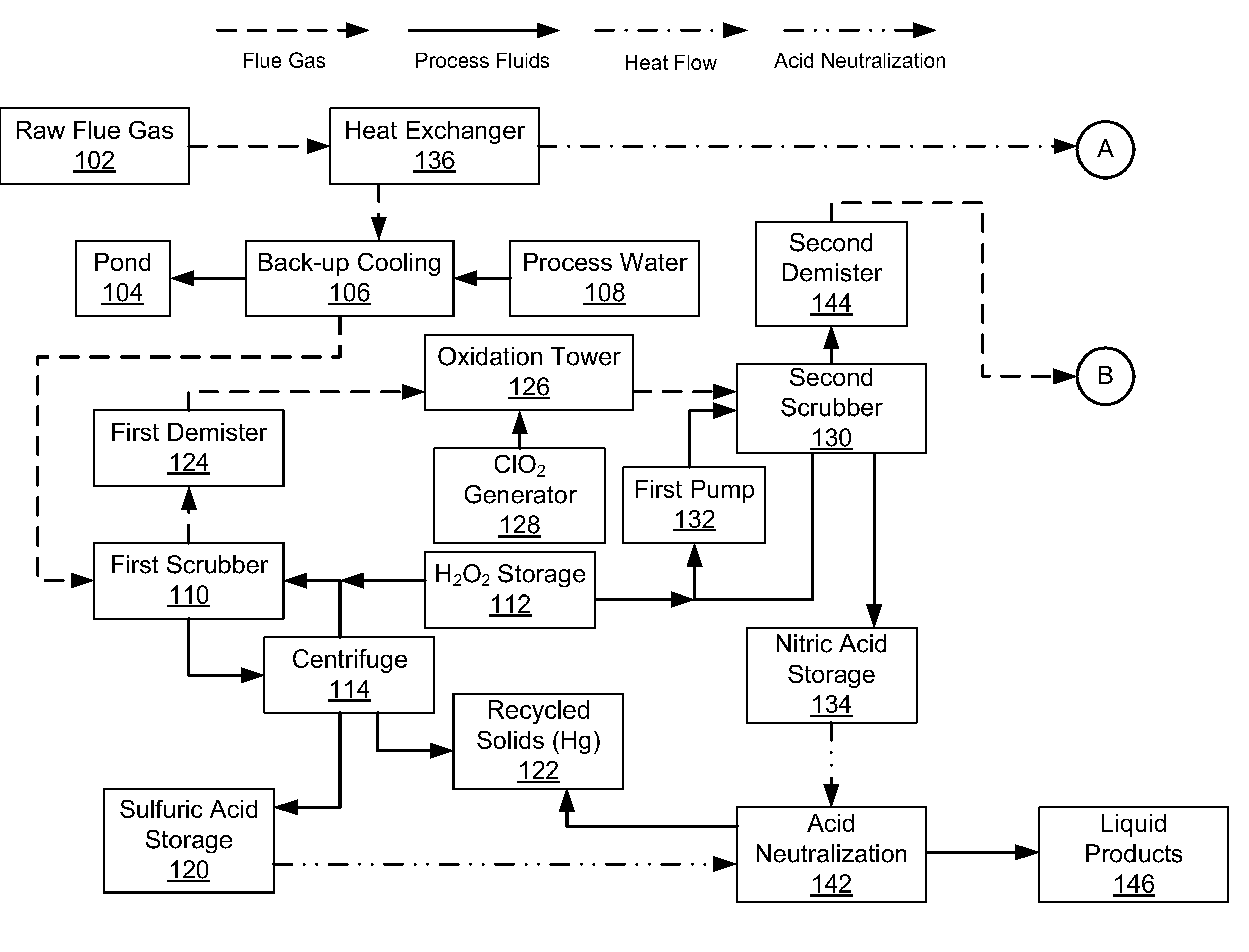
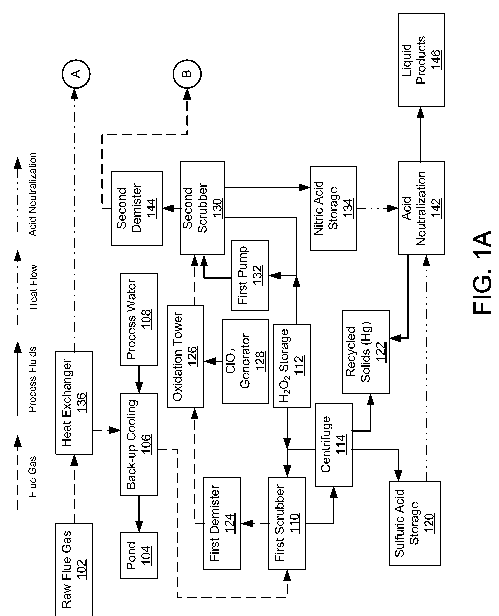
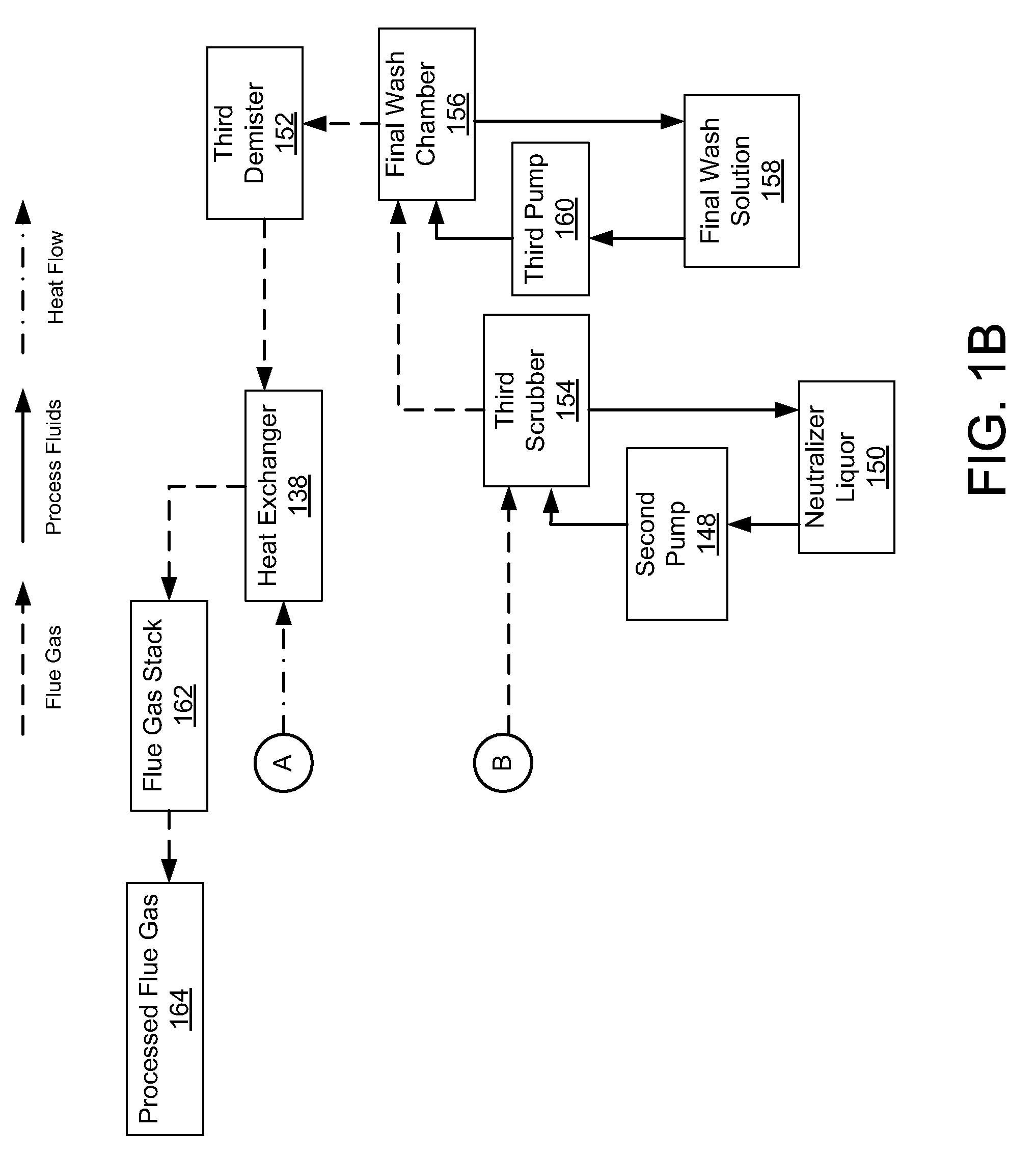
[0013]Emission control systems in accordance with the invention address environmental pollutants SOx, NOx, and mercury or other heavy metals. Such s...


PUM

PropertyMeasurementUnit
Concentrationaaaaaaaaaa
Levelaaaaaaaaaa

Abstract

Methods and apparatus utilizing chlorine dioxide and hydrogen peroxide are useful to reduce emissions of NOx, SOx, and heavy metals, e.g., mercury, emissions from combustion flue gas streams.

Description

ORIGIN OF THE INVENTION[0001]The invention described herein was made in part by an employee of the United States Government and may be manufactured and used by and for the Government of the United States for governmental purposes without the payment of any royalties thereon or therefor.TECHNICAL FIELD OF THE INVENTION[0002]The present invention relates generally to emission control and in particular to the control of emissions from combustion sources.BACKGROUND OF THE INVENTION[0003]Control of emissions from fossil fuel combustions sources addresses a major environmental problem. The Environmental Protection Agency (EPA) through the Clean Air Act regulates the emissions from fossil-fuel-fired power plants. Initial regulations were focused on oxides-of-nitrogen (NOx) and oxides-of-sulfur (SOx) emissions, but newer regulations will include provisions to control heavy metals (Hg, etc.) and carbon dioxide. In particular, elemental mercury emissions from coal-fired power plants are a maj...

Claims


Application Information

Patent Timeline
IPC IPC(8): F01N3/20C01G13/00G05D7/00C22B43/00
CPCB01D53/346B01D53/507B01D53/56B01D53/64B01D53/75B01D2251/10B01D2251/106B01D2257/602F23J15/02F23J2215/60F23J2219/40
Inventor PARRISH, CLYDE F.CHUNG, LANDY
Owner NASA
Why Eureka
Try Eureka