
Integrated mercury control system

a mercury control system and integrated technology, applied in the direction of emission prevention, separation processes, instruments, etc., can solve the problems of not taking into account, increasing the amount of activator used, and simply increasing the amount of sorbent used, so as to minimize mercury emissions, minimize pollutant gas emissions, and minimize mercury emissions

Inactive Publication Date: 2010-11-11
GENERAL ELECTRIC TECH GMBH
View PDF16 Cites 15 Cited by
  • Summary
  • Abstract
  • Description
  • Claims
  • Application Information

AI Technical Summary

Benefits of technology

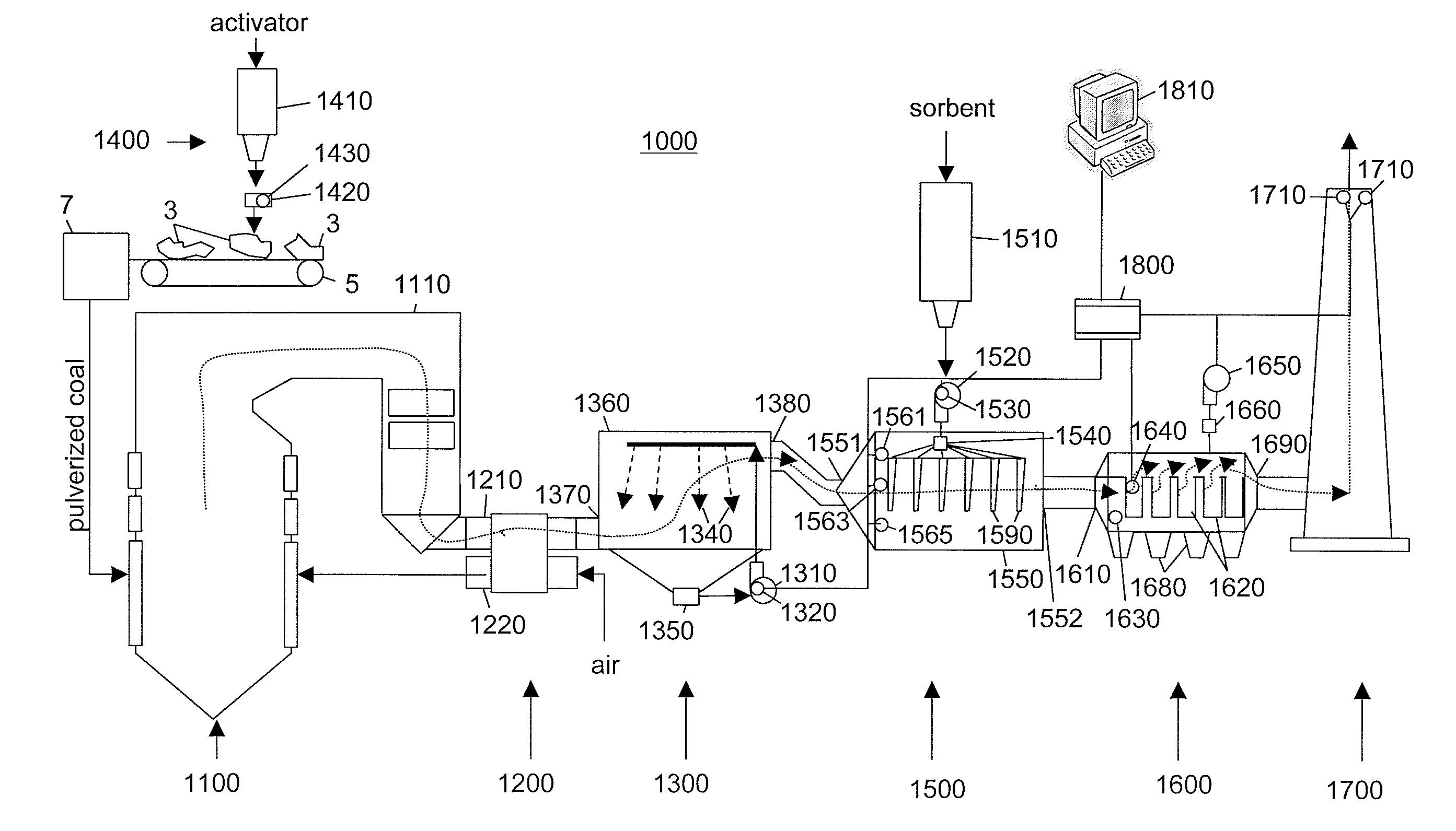
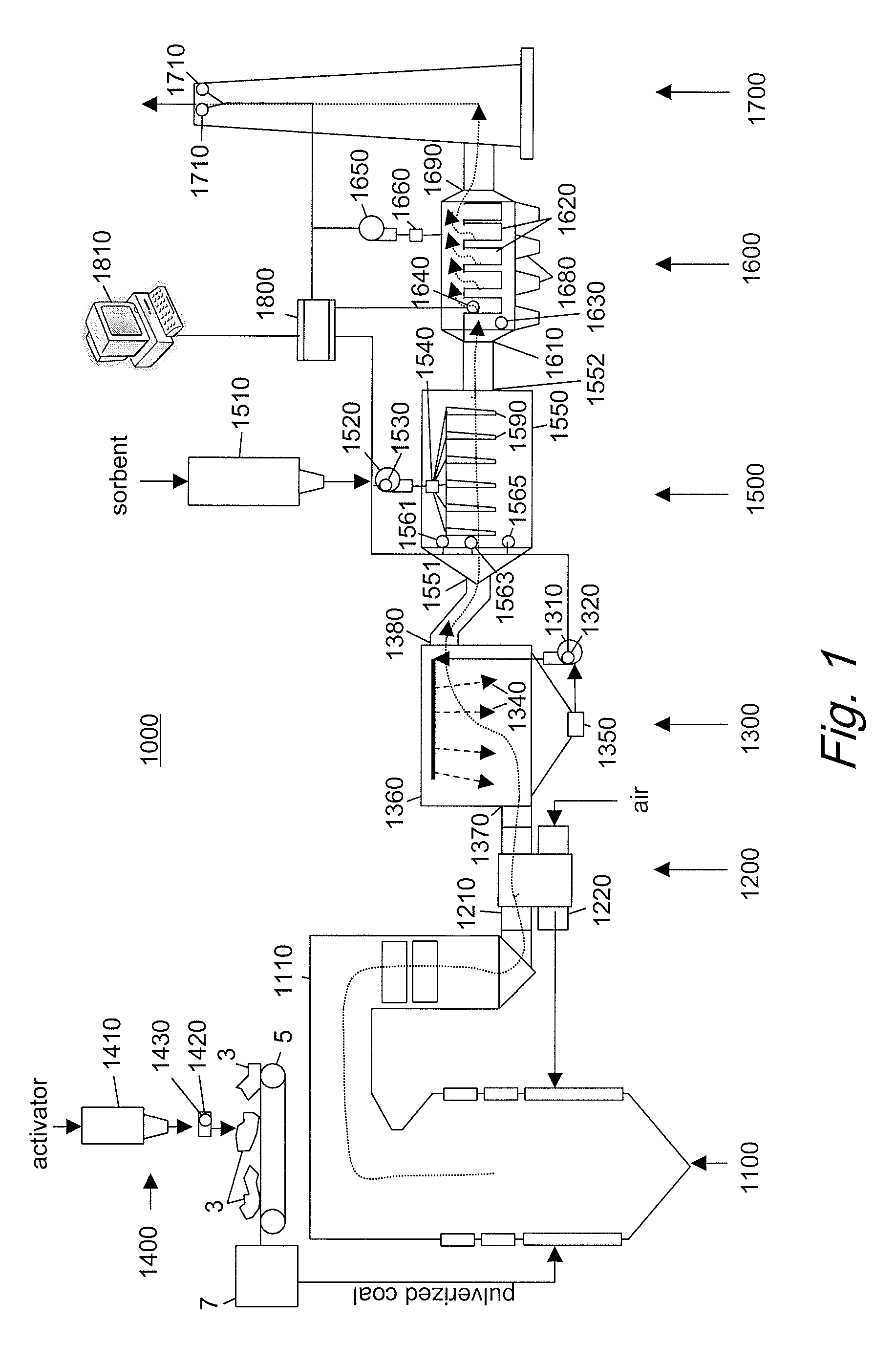
[0015]a controller [1800] coupled to the scrubber [1300], the sorbent injection subsystem [1500] and the stack sensor [1710] for reading the rate that neutralizer is provided into the flue gasses, the rate of the sorbent is dispersed by the sorbent injection subsystem, an amount of gaseous pollutant in the stack [1700], a unit cost of the neutralizer, the sorbent and for providing a signal adjusting the rate of neutralizer and sorbent dispersed to reduce said boiler operating costs while maintaining gaseous pollutant levels within predetermined acceptable levels.
[0036]It is another object of the present invention to provide an interactive system that monitors and controls system functioning to maximize filter bag life.

Problems solved by technology

When too much mercury is exiting the system, the system simply increases the amount of sorbent used.
Again, there are times when increasing the amount of activator used is not as effective as adjusting another input parameter.
These however, did not take into account additional parameters that may be varied to adjust the emissions of mercury from a plant, and did not optimize all the parameters.
They also did not optimize with respect to plant operation costs.
This results in waste and additional plant operation costs.

Method used


Image

  • Integrated mercury control system
  • Integrated mercury control system
  • Integrated mercury control system

Examples


Embodiment Construction

Theory

[0047]Solid particles suspended in flowing flue gases have been known to be separated from the remaining flue gasses with the use of fabric filters and / or electrostatic particle filters. Fabric filters physically stop particles of a given size or larger from passing through the fabric to escape. The particles are collected from the outside of the filter then disposed.

[0048]Electrostatic filters precipitate solid particles out of the flue gases by using electrostatic attraction.

[0049]Gaseous pollutants are more difficult than particulate matter to remove from escaping flue gasses. Mercury (Hg) is present in many fuels, such as coal. When coal is burned, Hg is released into its gaseous phase. Hg is a toxic pollutant and should be removed from the flue gasses.

[0050]Adsorption of gaseous pollutants, such as Hg, are based upon a) proximity of the gaseous pollutant molecules to the adsorption particles; and b) excitation of the pollutant gas molecules.

[0051]One method of removing ga...


PUM

PropertyMeasurementUnit
affinityaaaaaaaaaa
flow rateaaaaaaaaaa
lengthsaaaaaaaaaa

Abstract

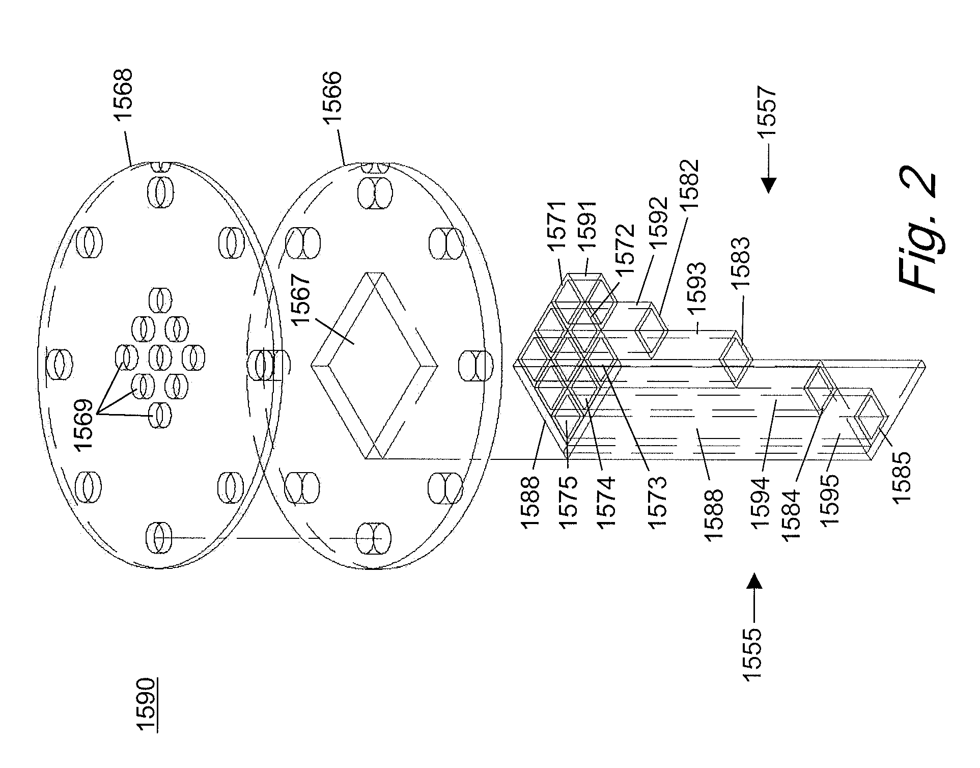
An integrated system [1000] is described for reducing operating costs of power plants while keeping gaseous pollutants in exhaust flue gasses, such as Mercury (Hg), below acceptable limits. Controller [1800] monitors and controls operation of a scrubber [1300], activator injection system [1400], sorbent injection system [1500] and a filter [1600]. Scrubber [1300] provides a neutralizer to remove SO2 emissions. Activator injection system [1400] provides and activator that increases affinity of the pollutant gasses for a sorbent. Sorbent injection system [1500] employs novel low friction injection lances [1590] that evenly distribute the sorbent particles. A filter [1600] collects the sorbent particles that cake onto filter bags [1620] that are periodically cleaned. A controller [1800] receives the costs of materials consumed and the filter bag life for the plant and performs an optimization of the multiple variables to minimize costs while keeping the pollutant emissions below a prescribed limit.

Description

TECHNICAL FIELD[0001]The present disclosure relates to a system for reducing gaseous pollutant emissions from a power plant, and more specifically an integrated optimization system for reducing gaseous pollutant emissions from a power plant while minimizing costs of plant operation.BACKGROUND[0002]Furnaces, such as commercial boilers, burn fuels that release gaseous pollutants, such as mercury into the atmosphere. Mercury condenses returns to the ground as a toxic contaminant. New regulations are proposed to greatly reduce the amount of mercury that can be released.[0003]Devices have been employed that reduce the amount of mercury released. One such device disperses activated carbon particles into the flue gasses to adsorb the Mercury gasses.[0004]When too much mercury is exiting the system, the system simply increases the amount of sorbent used. Sometimes other parameters that may be altered to achieve better results.[0005]An activator is used in addition to a sorbent to decrease m...

Claims


Application Information

Patent Timeline
Patent Type & Authority Applications(United States)
IPC IPC(8): F23J15/02B05B1/00B05B12/00
CPCB01D53/34B01D53/64B01D53/75B01D2257/302F23J15/006B01D2259/128F23J2217/101F23J2219/40G05B13/021B01D53/79F23J2215/20
Inventor MATTESON, DAVID J.SUTTON, JAMES P.TOBIASZ, REBECCA L.KOZLAK, MARTIN J.
Owner GENERAL ELECTRIC TECH GMBH
Learn More