Endoscope

Inactive Publication Date: 2008-10-02
OLYMPUS MEDICAL SYST CORP
View PDF9 Cites 54 Cited by
  • Summary
  • Abstract
  • Description
  • Claims
  • Application Information

AI Technical Summary

Benefits of technology

[0022]According to the present invention, the endoscope in which the small-diameter design

Problems solved by technology

However, in a central rotationally symmetric illumination means using a perfectly circular illumination lens and a light guide fiber whose tip is molded into a cy

Method used


Image

  • Endoscope
  • Endoscope
  • Endoscope

Examples


embodiment 1

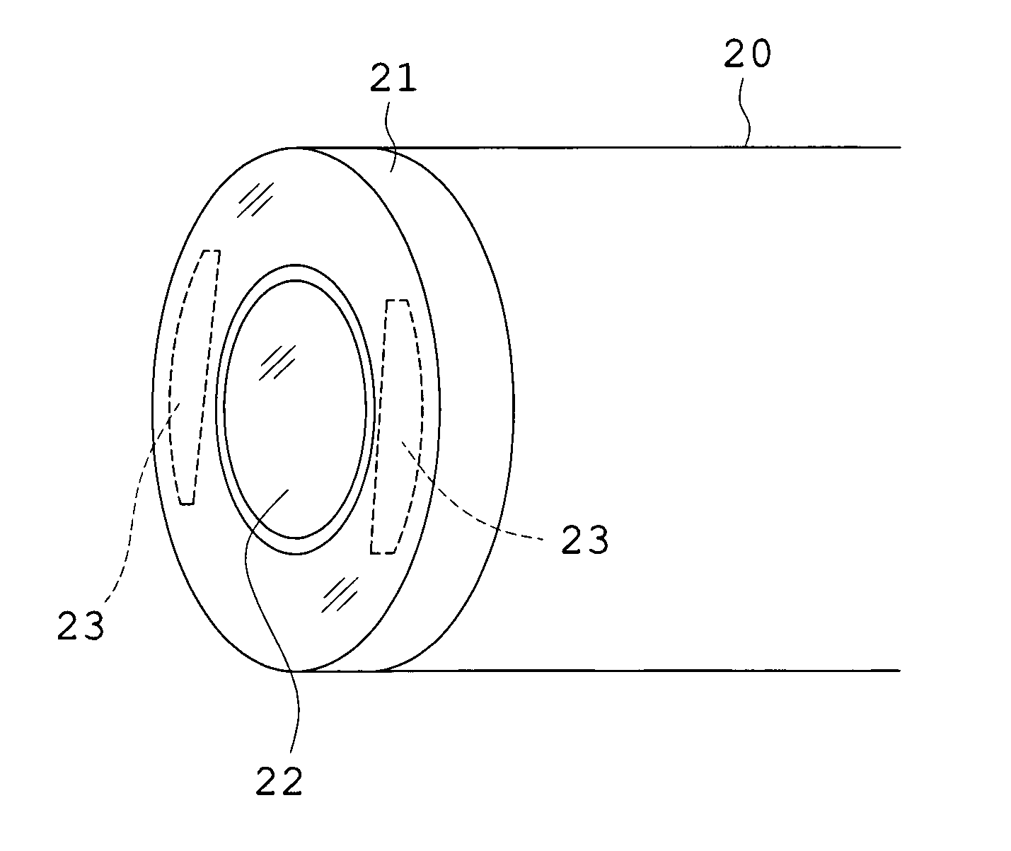
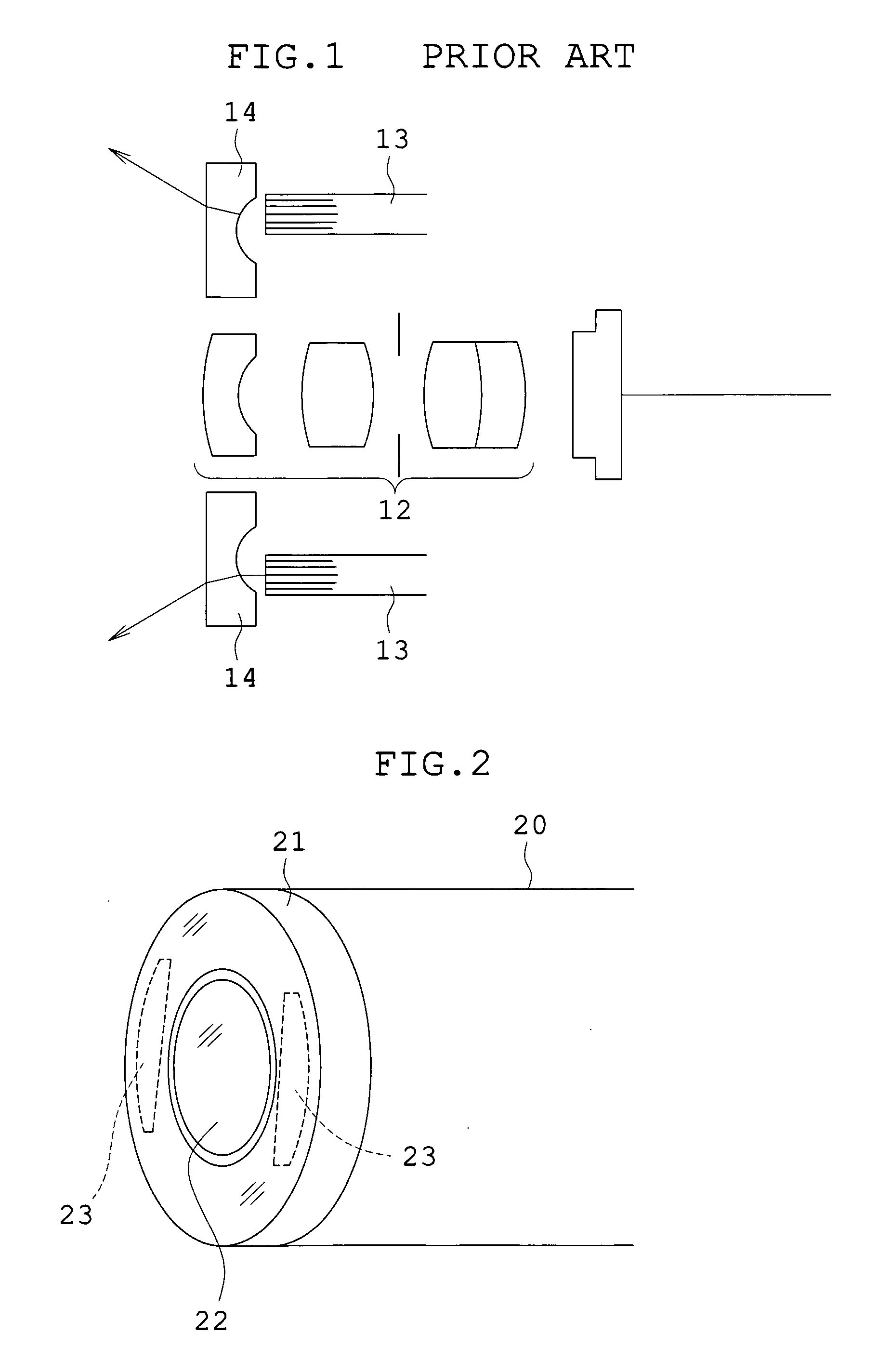
[0037]FIG. 2 shows the contour of the endoscope of this embodiment. An objective optical system 22 is incorporated in a distal end 20 of the endoscope so that it is exposed to the exterior, and light guides 23 are arranged around the objective optical system 22. A top cover 21 which is opposite to the exit end faces of the light guides 23, covers a part of the side surface of the distal end 20, and is made of transparent resin as a whole is fixed by cementation.

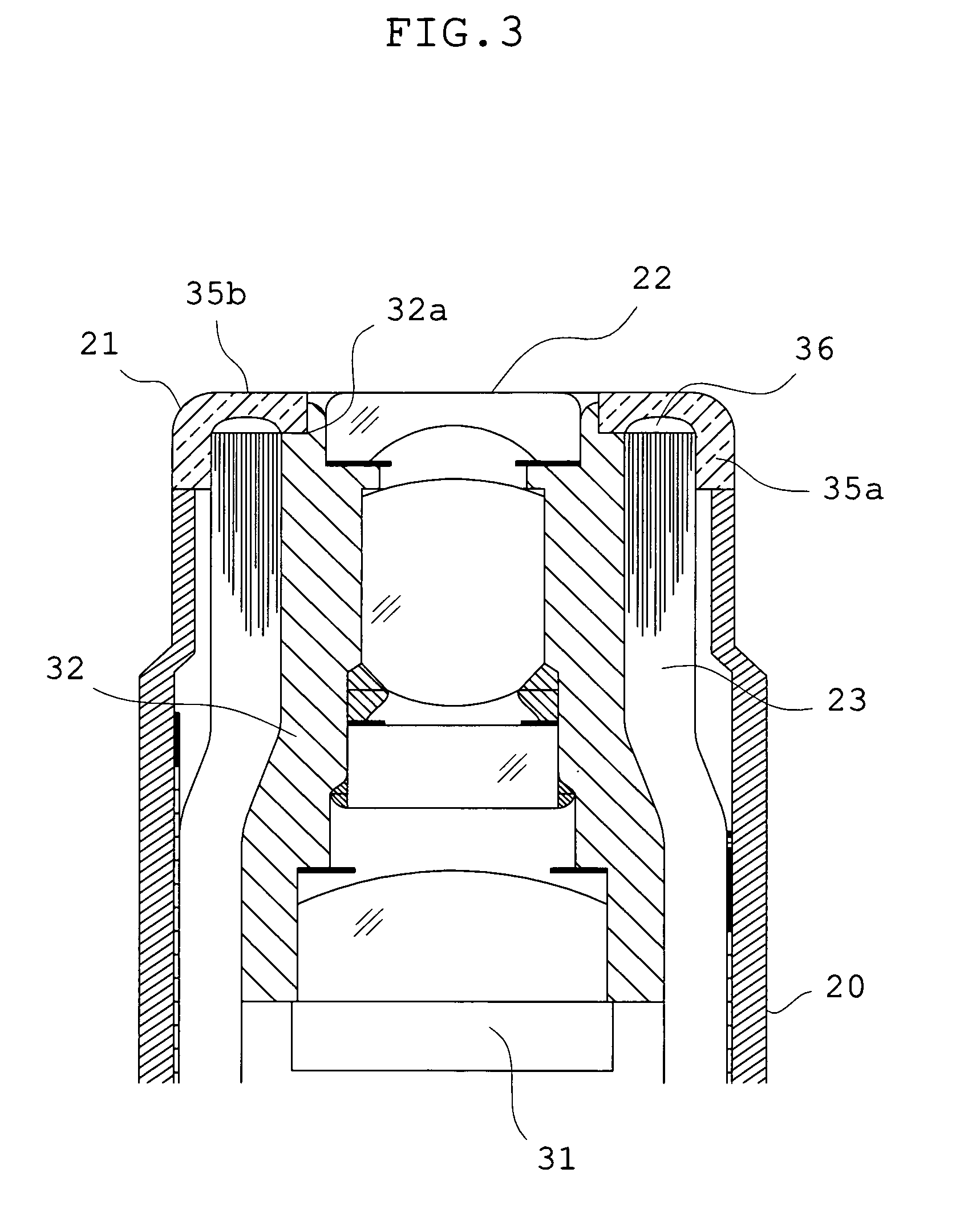
[0038]FIG. 3 shows the horizontal section of the distal end 20. At the distal end 20, an image sensor 31 with a laterally elongated imaging region is placed at the imaging position of the objective optical system 22 in a lens barrel 32.

[0039]The top cover 21 includes a peripheral barrel portion 35a covering the side surface of the distal end 20 and an annular portion 35b configured integrally with the peripheral barrel portion 35a and is provided with an illumination light diffusing portion 36 including an annular surface at ...

embodiment 2

[0045]The structure of the endoscope of this embodiment is shown in FIG. 7. Parts not shown in this figure are the same as in Embodiment 1 and their explanation is omitted. In Embodiment 2, portions of the top cover 21 that are not opposite to the exit end faces 52a of the light guides 23 are provided as plane portions 83. It is only necessary that illumination light diffusing portions 81 are provided at positions opposite to the exit end faces of the light guides. The plane portions 83 are provided like Embodiment 2 and thereby the property of cementation between the top cover 21 and the lens barrel can be improved.

embodiment 3

[0046]FIG. 8 illustrates the section of the illumination light diffusing portion of the endoscope of this embodiment. In Embodiment 3, a plurality of concentric minute grooves 91 are superposed on the annular surface, with the center of the top cover 21 as an axis of symmetry, and are configured as the illumination light diffusing portion. It is desirable that the width of each groove is 0.1 mm or less. By the function of the plurality of minute grooves 91, the negative refracting power is increased in the lateral direction, but it is little changed in the vertical direction, and thus a more laterally elongated illumination area is obtained. As illustrated in FIG. 9, even when only a plurality of concentric minute grooves 102 are configured as the illumination light diffusing portion, the same effect is brought about.


PUM


Abstract

An endoscope incorporates an objective optical system and an image sensor at its distal end and has light guides around the objective optical system. In this case, when a direction parallel to the major side of an imaging region of the image sensor is taken as a lateral direction, exit end faces of the light guides are arranged only in the lateral direction of the objective optical system, a top cover is placed opposite to the exit end faces, and an illumination light diffusing portion is provided at the position of the top cover opposite to the exit end faces. Whereby, the endoscope in which the small-diameter design of the distal end is attained and the loss of emergent light is minimized can be provided.

Description

[0001]This application claims benefits of Japanese Application No. 2007-86219 filed in Japan on Mar. 29, 2007, the contents of which are incorporated herein by reference.BACKGROUND OF THE INVENTION[0002]1. Field of the Invention[0003]This invention relates to an endoscope, and in particular, to a small-diameter endoscope.[0004]2. Description of Related Art[0005]Generally, in an endoscope, its body is constructed with a slender insertion tube section and a manipulation section provided at a proximal end of the insertion tube section. The insertion tube section includes an objective optical system for forming an image of an observation object, an image sensor for converting the image into an electric signal, and an illumination means for supplying illumination light to the observation object, provided inside the insertion tube section at a distal end.[0006]There are a number of various endoscopes in which channels into which treatment tools are inserted and channels for water feed and...

Claims


Application Information

Patent Timeline
IPC IPC(8): A61B1/06
CPCA61B1/00096A61B1/00101A61B1/00165A61B1/05A61B1/07
Inventor INOUE, TAKAHIRO
Owner OLYMPUS MEDICAL SYST CORP
Why Eureka
Try Eureka