4Pi microscope

a microscope and microscope technology, applied in the field of 4pi microscopes, can solve the problems of unfavorable interferometry beam path coupling of excitation light, detected light, lost, etc., and achieve the effect of improving excitation and/or detection efficiency

Inactive Publication Date: 2008-11-18
LEICA MICROSYSTEMS CMS GMBH
View PDF10 Cites 3 Cited by
  • Summary
  • Abstract
  • Description
  • Claims
  • Application Information

AI Technical Summary

Benefits of technology

[0007]It is, therefore, an object of the present invention to provide a

Problems solved by technology

The inherent disadvantage of the known double-confocal scanning microscopes (4Pi microscopes) is that unused excitatio

Method used


Image

  • 4Pi microscope
  • 4Pi microscope

Examples


Embodiment Construction

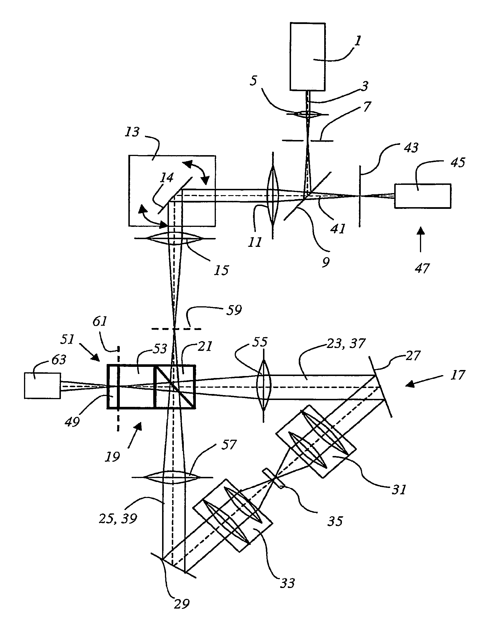
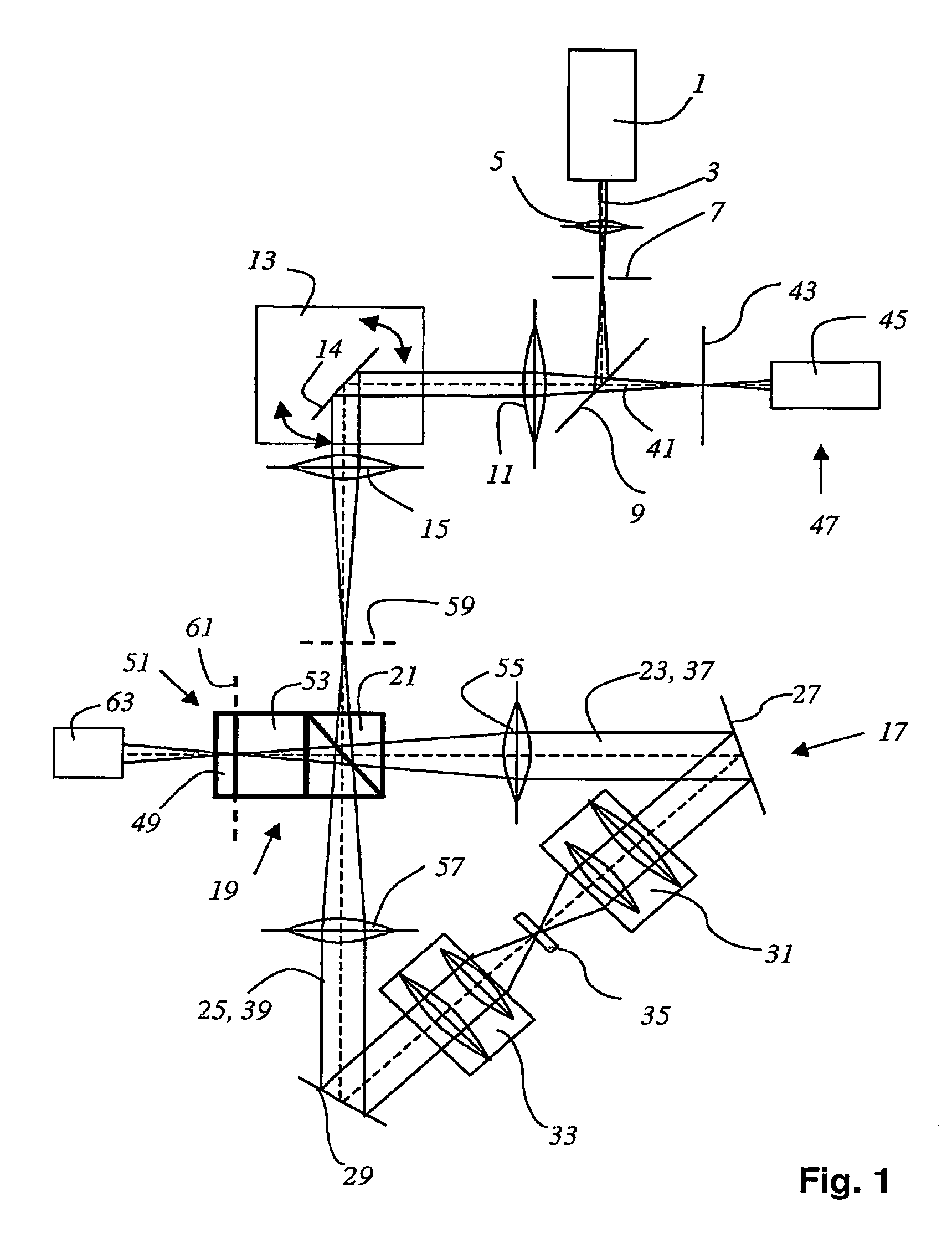
[0018]FIG. 1 illustrates a confocal 4Pi microscope according to the present invention, including a light source 1 which produces an illumination light beam 3. Illumination light beam 3 is focused with the aid of a lens system 5 at illumination pinhole 7, passes through the same, and arrives at main beam splitter 9. Main beam splitter 9 reflects illumination light beam 3 through further lens system 11 for beam deflection device 13, which contains a gimbal-mounted scanning mirror 14. Illumination light beam 3 passes through scanning lens system 15 and is coupled into interferometer 17. For incoupling optics, interferometer 17 includes an optical element 19, designed as beamsplitter cube 21. Beamsplitter cube 21 divides illumination light beam 3 into a first illumination-light partial beam 23 and a second illumination-light partial beam 25, which are directed by path-folding mirrors 27 and 29, respectively, and through microscope objectives 31 and 33, respectively, to specimen 35. The ...


PUM


Abstract

A 4Pi microscope provided with an interferometer wherein two lenses (31, 33) are arranged in such a way that they are opposite to each other on different sides of a sample plane (35); also comprising an optical element (19) which is used to inject illuminating light (3) into the interferometer and/or used to discharge detection light (41) from the interferometer and to deflect a detection beam path, containing a reflecting means (51) which reflects illuminating light discharged by the optical element back into the interferometer and/or which allows detection light which is deflected onto the deflection beam to pass, also reflecting other discharged detection light which is not deflected onto the detection beam path into the interferometer.

Description

[0001]The present invention relates to a 4Pi microscope having an interferometer in which two objectives are positioned to oppose one another on different sides of an object plane, and having an optical element for coupling illuminating light into the interferometer and / or for coupling detected light out of the interferometer and for directing it into a detection beam path.BACKGROUND[0002]In scanning microscopy, a specimen is illuminated by a light beam in order to observe the reflected light or emitted fluorescent light emanating from the specimen. The focus of an illumination light beam is moved in an object plane using a controllable beam deflection device, generally by tilting two mirrors; the deflection axes usually being perpendicular to one another so that one mirror deflects in the x direction and the other in the y direction. Galvanometer positioning elements are used, for example, for tilting the mirrors. The luminous flux coming from the object is measured as a function o...

Claims


Application Information

Patent Timeline
IPC IPC(8): G01B11/02G02B21/00G02B26/00
CPCG02B21/0056G02B26/001
Inventor LEIMBACH, VOLKERRYGIEL, REINER
Owner LEICA MICROSYSTEMS CMS GMBH
Why Eureka
Try Eureka