Rare-earth doped optical fiber, method of producing the same, and fiber laser

a technology of optical fiber and rare earth, applied in the field of rare earth doped optical fiber, can solve the problems of difficult to maintain manufacturing stability, increase the loss of optical fiber, and reduce the loss of oscillation light, so as to improve the oscillation efficiency, reduce the loss of optical fiber, and increase the optical loss of optical fiber.

Active Publication Date: 2009-09-24
THE FUJIKURA CABLE WORKS LTD
View PDF0 Cites 4 Cited by
  • Summary
  • Abstract
  • Description
  • Claims
  • Application Information

AI Technical Summary

Benefits of technology

[0058]The general optical fibers of the related art that have been produced without the processes (b) to (d) do not have the preferable rare-earth dopant distribution in the core thereof. Accordingly, as compared to exemplary embodiments of the invention, the related art optical fibers do not provide advantageous effects.
[0059]The rare-earth dopant distribution of the rare-earth doped optical fiber of exemplary embodiments of the invention is controlled to be in the range defined by Equation (1) and / or (2). In this manner, the photodarkening, which is a phenomenon of increasing optical loss of the optical fiber due to high excitation power incident on the optical fiber, can be prevented, and thus the loss of the oscillation light can be reduced.
[0061]Exemplar embodiments of the invention have multiple clad layers to cause the multimode excitation light to be propagated in the clad. In this manner, the excitation efficiency can be kept high and the rare-earth dopant distribution can be flexibly designed. Furthermore, the loss of the oscillation light can also be reduced.EXAMPLES
[0062]Hereinafter, exemplary optical fibers and methods of producing the same according to exemplary embodiments of the invention will be described. The invention, however, is not limited to those described and may be changed without departing from the technical idea thereof.
[0063]A preform of the rare-earth doped optical fiber is produced in accordance with the aforementioned preform design process. The preform is then drawn to provide a rare-earth doped optical fiber (i.e., the rare-earth doped double-clad fiber herein) and is evaluated.

Problems solved by technology

Accordingly, the photodarkening may occur depending on the clustering, which may increase the optical fiber loss.
As a result, the transmission loss in spontaneous emission and / or stimulated emission may increase, which may cause a decrease in the power output.
It is thus difficult to maintain manufacturing stability.
Furthermore, since aluminum may increase the refractive index, it is difficult to apply multi-component glass particles having high-concentration aluminum doped thereto and an optical amplifier fiber using the same, which are disclosed in Published Japanese Translation No. 2002-526373 of the PCT International Publication in which the DND process is employed, to a core with a low relative index difference Δ (“low Δ core”).

Method used


Image

  • Rare-earth doped optical fiber, method of producing the same, and fiber laser
  • Rare-earth doped optical fiber, method of producing the same, and fiber laser
  • Rare-earth doped optical fiber, method of producing the same, and fiber laser

Examples


example 1

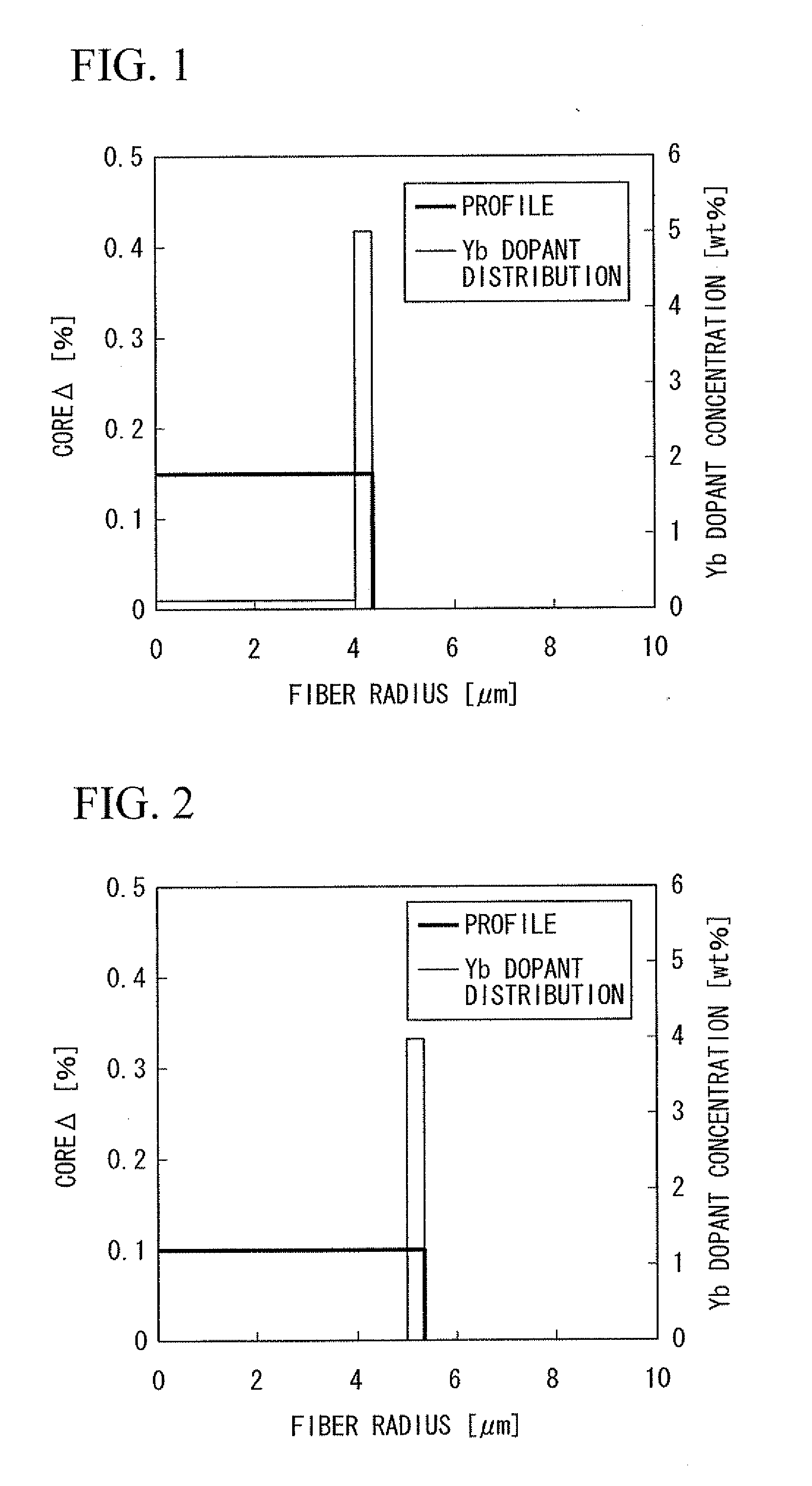
[0064]An optical fiber core preform according to the design shown in FIG. 1 is obtained in the following manner. A glass soot is formed by depositing in a modified chemical vapor deposition (MCVD) process, and then aluminum (Al) and ytterbium (Yb) are doped to the glass soot in a solution doping process according to the design shown in FIG. 1. The doped glass soot is subject to sintering and collapse processes to prepare a core preform. Then a clad is formed on a surface of the core preform in a jacketing process. In this manner, an optical fiber preform (having a core Δ of 0.15% and a core diameter of 4.4 μm) that has the refractive index profile and the Yb dopant distribution shown in FIG. 1 is obtained.

[0065]The preform is then drawn in a drawing device. Low-refractive-index polymer resin is deposited to cover the optical fiber preform to provide a rare-earth doped double-clad fiber.

[0066]The core Δ (i.e., the difference in relative refractive index between the core and the first...

example 2

[0069]An optical fiber core preform according to the design shown in FIG. 2 is obtained in the following manner. A glass soot is formed by depositing in a VAD process, and then aluminum (Al) and ytterbium (Yb) are doped to the glass soot in a solution doping process according to the design shown in FIG. 2. The obtained glass soot is subject to a sintering process to prepare a core preform. Then a clad is formed on a surface of the core preform in an outside vapor deposition process. In this manner, an optical fiber preform (having a core A of 0.10% and a core diameter of 5.4 μm) that has the refractive index profile and the Yb dopant distribution shown in FIG. 2 is obtained.

[0070]The preform is then drawn in a drawing device. Low-refractive-index polymer resin is deposited to cover the optical fiber preform to provide a rare-earth doped double-clad fiber.

[0071]The core Δ is provided by aluminum (Al) and germanium (Ge) doped to the core.

[0072]A value calculated by Equation (2) is 0.2...

example 3

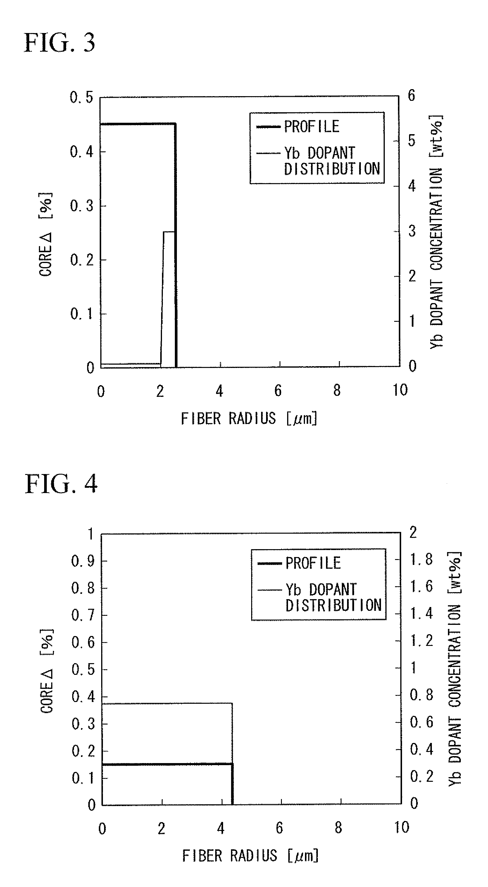
[0074]An optical fiber core preform according to the design shown in FIG. 3 is obtained in the following manner. A glass soot is formed by depositing in a plasma chemical vapor deposition (PCVD) process, and then aluminum (Al) and ytterbium (Yb) are doped to the glass soot in a solution doping process according to the design shown in FIG. 3. The obtained glass soot is subject to a sintering process to prepare a core preform. A clad is formed on a surface of the core preform in an outside vapor deposition process. In this manner, an optical fiber preform (having a core Δ of 0.45% and a core diameter of 2.5 μm) that has the refractive index profile and the Yb dopant distribution shown in FIG. 3 is obtained.

[0075]The preform is then drawn in a drawing device. Low-refractive-index polymer resin is deposited to cover the optical fiber preform to provide a rare-earth doped double-clad fiber.

[0076]The core Δ is provided by aluminum (Al), germanium (Ge), and fluoride (F) doped to the core.

[...


PUM

PropertyMeasurementUnit
core diameteraaaaaaaaaa
core Δaaaaaaaaaa
wavelengthaaaaaaaaaa

Abstract

A rare-earth doped optical fiber that includes a core and one or more clad layers surrounding the core, in which the core has a rare earth dopant, and a relationship of Equation (1) is satisfied:0<∫r0rcD(r)·Pp2(r)·Ps2(r)rr∫r0rcD(r)·Pp2(r)rr≤0.35(1)where Pp(r) represents an electric field distribution in an exciting wavelength, Ps(r) represents an electric field distribution in wavelengths of spontaneous emission and / or stimulated emission carried in the core, D(r) (mass %) represents a rare-earth dopant distribution, ro represents a core center, and rc represents a core diameter.

Description

CROSS-REFERENCE TO RELATED APPLICATION[0001]This application claims priority from Japanese Patent Application No. 2008-064715, filed Mar. 13, 2008 in the Japanese Patent Office, the disclosure of which is incorporated herein by reference in its entirety.BACKGROUND OF THE INVENTION[0002]1. Field of the Invention[0003]Apparatuses and methods consistent with the present invention relate to a rare-earth doped optical fiber.[0004]2. Description of the Related Art[0005](I) A rare-earth doped double-clad optical fiber has been proposed wherein the optical fiber includes: an optical fiber core (i.e., a rare-earth doped core) of silica glass doped with a rare-earth element, such as erbium (Er) or ytterbium (Yb); a first clad surrounding the core, to which a pumping beam for efficient excitation of the rare-earth element is injected; and a second clad provided on the first clad to form an outermost layer, the second clad consisting of a low-refractive-index polymer resin having a refractive i...

Claims


Application Information

Patent Timeline
Patent Type & Authority Applications(United States)
IPC IPC(8): H01S3/30G02B6/036B29D11/00
CPCH01S3/0672H01S3/06716
Inventor OKADA, KENJI
Owner THE FUJIKURA CABLE WORKS LTD
Why Eureka
Try Eureka