Ophthalmic laser treatment apparatus

Inactive Publication Date: 2008-10-02
NIDEK CO LTD
View PDF6 Cites 29 Cited by
  • Summary
  • Abstract
  • Description
  • Claims
  • Application Information

AI Technical Summary

Benefits of technology

[0007]The present invention has been made in view of the above circumstances and has an object to provide an ophthalmic laser treatment apparatus capable of irradiating a treatment laser beam having a beam characteristic adequate for treatment to an affected part and also of changing a spot size by a simple structure.

Problems solved by technology

This may cause uneven burning in the fundus photocoagulation treatment, and hence a uniform coagulation spot could not be formed.
The above proposed techniques have disadvantages such as a decrease in fiber transmittance, and a difficulty in placing and adjusting a mechanism for oscillating the multimode fiber.
Further, in the case of using a single mode fiber instead of the multimode fiber, a beam profile at an emission end face of the single mode fiber is Gaussian, which would cause excessive coagulation in a center area of an irradiated part of an affected part.
Such an optical system is difficult to manufacture.

Method used


Image

  • Ophthalmic laser treatment apparatus
  • Ophthalmic laser treatment apparatus
  • Ophthalmic laser treatment apparatus

Examples


Embodiment Construction

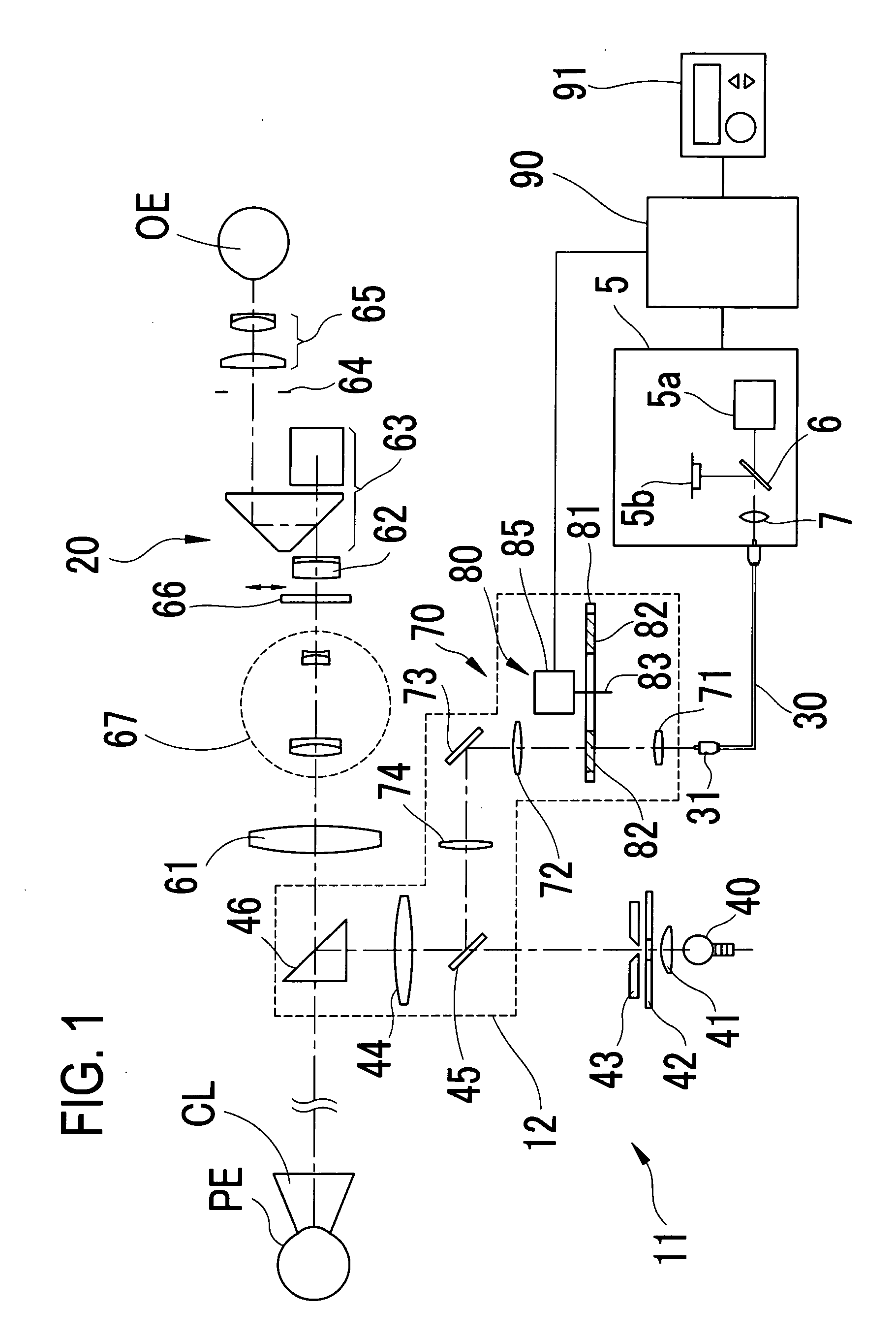
[0017]A detailed description of a preferred embodiment of the present invention will now be given referring to the accompanying drawings. FIG. 1 is a schematic side view of an ophthalmic laser treatment apparatus of the present embodiment. In this embodiment, an apparatus for photocoagulating an affected part such as a fundus of a patient's eye is exemplified.

[0018]The laser apparatus includes: a slit lamp constituted by an observation unit 20 having a binocular microscope and an illumination section 11; a main box 5 in which a laser source is located; an optical fiber 30 for transmitting a laser beam from the main box 5; and a laser delivery optical system 12 for irradiating the laser beam emerging from the optical fiber 30 to the affected part such as the fundus, and others.

[0019]An observation optical system placed in the observation unit 20 includes an objective lens 61 used in common between right and left observation optical paths, a variable power lens unit 67, an operator pr...


PUM


Abstract

An ophthalmic laser treatment apparatus comprises: a laser source that emits a laser beam for treatment of an affected part of a patient's eye; an optical fiber that transmits the laser beam emitted from the laser source; and a delivery optical system that irradiates the laser beam emitted from the optical fiber to the affected part of the patient's eye, the delivery optical system including: a plurality of diffraction optical elements each being configured to shape a beam profile of the laser beam at an emission end face of the optical fiber into a beam profile having one of a uniform intensity and a lower intensity in the center than on the periphery on the affected part and also to shape the laser beam to have a different spot size on the affected part of the patient's eye; and a changing unit which selectively disposing one of the diffraction optical elements on an optical path.

Description

BACKGROUND OF THE INVENTION[0001]1. Field of the Invention[0002]The present invention relates to an ophthalmic laser treatment apparatus arranged to irradiate a laser beam to a patient's eye for treatment.[0003]2. Description of Related Art[0004]An ophthalmic laser treatment apparatus arranged to irradiate a laser beam to a patient's eye includes a laser source which emits a treatment laser beam, an optical fiber for transmitting the laser beam from the laser source, and a delivery optical system provided with a variable power optical system for focusing the laser beam transmitted through the optical fiber at a spot size adequate for treatment purposes. An optical fiber used in a photocoagulation treatment laser apparatus is usually a multimode fiber having a core diameter of about 50 μm. Further, a delivery unit is provided with a variable zoom optical system for changing the laser spot irradiated on the fundus in a range of 50 μm to 500 μm. In laser iridotomy, the magnification of...

Claims


Application Information

Patent Timeline
IPC IPC(8): A61F9/008A61B18/20
CPCA61B2018/2035A61F2009/00863A61F9/00821A61F9/008A61B18/22A61B2018/205545
Inventor MURAKAMI, NAHOITO, KOICHI
Owner NIDEK CO LTD
Why Eureka
Try Eureka