
Steering system

Active Publication Date: 2008-10-02
HONDA MOTOR CO LTD
View PDF5 Cites 78 Cited by
  • Summary
  • Abstract
  • Description
  • Claims
  • Application Information

AI Technical Summary

Benefits of technology

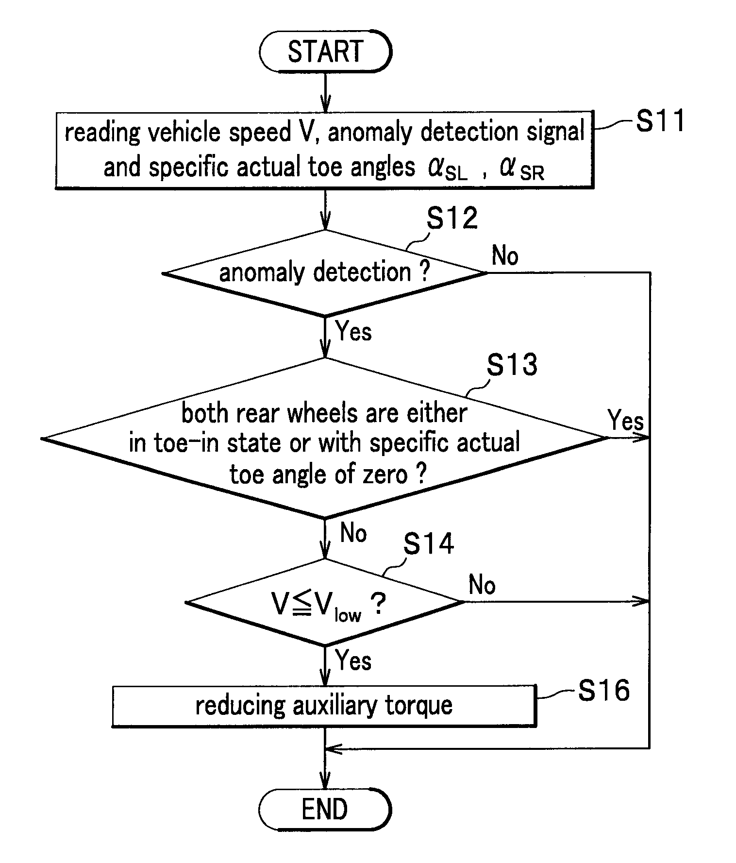
[0020]In the above-mentioned steering system, it is preferable that each of the toe angle changers includes the toe angle changer anomaly detection unit, the steering controller includes an auxiliary torque calculating unit configured to calculate the target value of the auxiliary torque, and the steering controller reduces the calculated target value of the auxiliary torque when the steering controller receives an anomaly detection signal from the toe angle changer anomaly detection unit.
[0022]In the above-mentioned steering system, it is preferable that each of the toe angle changers includes a toe angle detection unit for detecting the toe angle of the corresponding rear wheel and the toe angle changer anomaly detection unit, the steering controller includes a damping control part configured to calculate a compensation value for increasing or reducing the viscosity in the electric power steering device, and when the toe angle changer anomaly detection unit detects an abnormal state, in the case where the left and right rear wheels are toed in, the compensation value is made smaller to reduce the viscosity, and in the case where the left and right rear wheels are toed out, the compensation value is made larger to increase the viscosity.

Problems solved by technology

In the vehicle steering system for controlling vehicle properties by performing drive control of toe angle of rear wheels (RTC: Rear Toe Control), drive control by RTC may be failed (drive control by RTC may be in an abnormal state).
In this case, it becomes impossible to control the rear wheels, and the toe angle of rear wheels become fixed, leading to change in a yaw rate gain of the vehicle.
Especially, in the case of the anomaly, such as toe-out or antiphase failure, under a high yaw rate gain, the vehicle tends to be unstable, and thus stabilizing the vehicle body is highly demanded.
As a result, the reaction force value based on the feedback, which is supposed to be determined in accordance with the vehicle properties, cannot be properly altered.
When the vehicle properties has changed due to failure of the drive control by RTC, the vehicle tends to be unstable, but the conventional technique cannot respond to the change, leading to poor stabilization of the vehicle.
In addition, when the toe angle changer is in an abnormal state, for example, when the toe angle changer is locked with the wheels toed out or with an antiphase control state, and the vehicle runs at a higher speed, the vehicle behavior becomes unstable.
Moreover, if the locking as described above occurs when the vehicle runs at a low speed, the driver may not sense anomaly (may feel as usual), due to the assisting effect by auxiliary torque in the electric power steering device.
However, a sudden change in the steering torque in response to the anomaly detection of the toe angle changer will give an awkward feeling to the driver.
Also in the techniques disclosed in Patent Documents 3 and 4, when the toe angle changer is in an abnormal state, the toe angles of rear wheels are fixed and the reaction force properties are changed, which may give unnatural steering feeling to the driver.
In the technique disclosed in Patent Document 1, when the power steering device is in an abnormal state, such as no auxiliary torque is output from the power steering device, the operational reaction force on the steering wheel becomes larger than that in the normal state, leading to delay in steering wheel operation by the driver.
If the toe angle changer is normally acted under such a condition, the turnability is not reduced in response to the reduced steerability, leading to a discomfort to the driver.

Method used


Image

  • Steering system
  • Steering system
  • Steering system

Examples


first embodiment

1. Configuration of Steering System

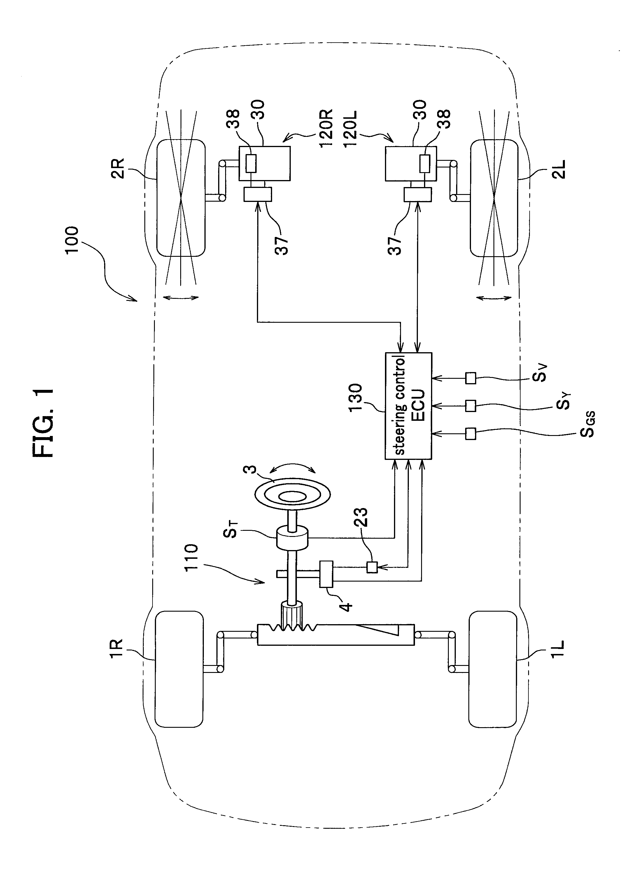
[0057]As shown in FIG. 1, a steering system 100 includes an electric power steering device 110 having an electric motor 4, which is configured to assist steering of front wheels 1L, 1R by a steering wheel 3; toe angle changers 120L, 120R configured to independently change respective toe angles of rear wheels 2L, 2R by respective actuators 30, in accordance with a turning angle of the front wheels 1L, 1R by the electric power steering device 110 and a vehicle speed; a steering controller (hereinbelow, referred to as “steering control ECU (Electronic Control Unit)”) 130 configured to control the electric power steering device 110 and the toe angle changers 120L, 120R; and various sensors, including a vehicle speed sensor SV, a yaw rate sensor SY (yaw rate detection unit) and a lateral acceleration sensor SGS.

2. Configuration of Electric Power Steering Device

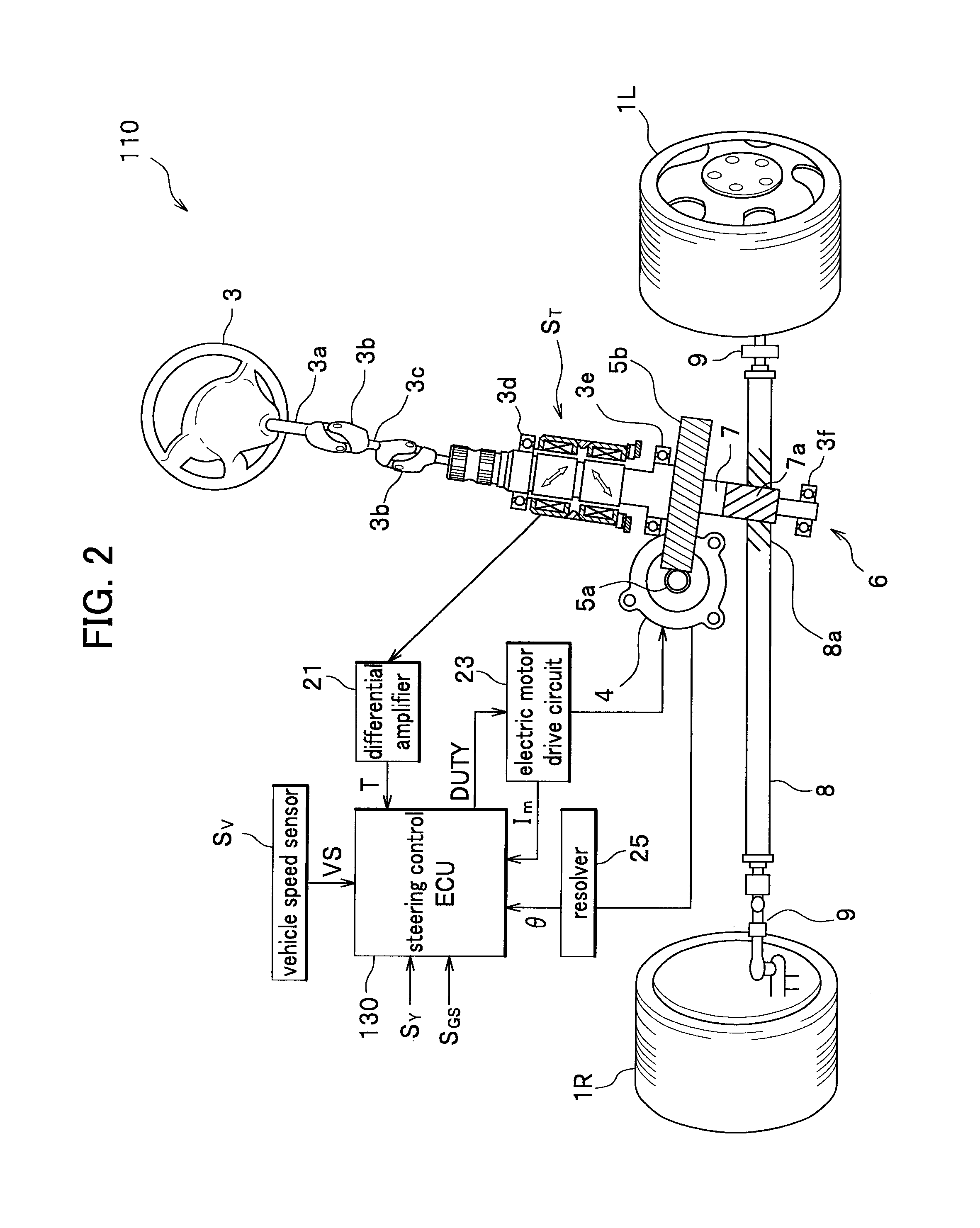
[0058]The electric power steering device 110 includes, as shown in FIG. 2, the steering wheel ...

second embodiment

[0161]A second embodiment of the present invention will be described with reference to FIGS. 3, 4, and 10-15. It should be noted that components which are the same as those illustrated in the above-mentioned embodiment are designated with the same reference characters, and thus a duplicate description is omitted, and that components which are equivalent, corresponding or similar to those illustrated in the above-mentioned embodiment, are designated with the same reference characters with a single prime (′), and will be described in detail when necessary.

[0162]FIG. 10 is a schematic diagram of a four-wheel vehicle having a steering system according to a second embodiment of the present invention.

[0163]FIG. 11 is a diagram of an electric power steering device in the steering system.

1. Configuration of Steering System

[0164]As shown in FIG. 10, a steering system 100′ of the second embodiment includes an electric power steering device 110′, toe angle changers 120L′, 120R′, a steering con...

third embodiment

[0222]A third embodiment of the present invention will be described with reference to FIGS. 3, 6A-6C, 12, 15 and 18-24. It should be noted that components which are the same as those illustrated in the above-mentioned embodiments are designated with the same reference characters, and thus a duplicate description is omitted, and that components which are equivalent, corresponding or similar to those illustrated in the above-mentioned embodiments, are designated with the same reference characters with a double prime (″), and will be described in detail when necessary.

[0223]FIG. 18 is a schematic diagram of a four-wheel vehicle having a steering system according to a third embodiment of the present invention. FIG. 19 is a diagram of an electric power steering device in the steering system.

1. Configuration of Steering System

[0224]As shown in FIG. 18, a steering system 100″ of the third embodiment includes an electric power steering device 110″, toe angle changers 120L″, 120R″, a steerin...


PUM


Abstract

A steering system includes: an electric power steering device which includes a steering unit of front wheels having an electric motor for generating an auxiliary torque in accordance with at least a steering torque and for transmitting the auxiliary torque to the steering unit; toe angle changers for changing toe angles of rear wheels in accordance with at least a front wheel turning angle and a vehicle speed; and a steering controller for controlling the electric power steering device and the toe angle changer. The steering system further includes a toe angle changer anomaly detection unit and / or an electric power steering device anomaly detection unit, and when a toe angle changer abnormal state is detected, an auxiliary torque target value and / or a viscosity in the electric power steering device is controlled, and when an electric power steering device abnormal state is detected, the toe angle changer is controlled.

Description

CROSS-REFERENCE TO RELATED APPLICATIONS[0001]This application claims the foreign priority benefit under Title 35, United States Code, section 119 (a)-(d), of Japanese Patent Application Nos. 2007-080485, 2007-084605, 2007-088012 and 2007-104508, filed on Mar. 27, 28 and 29, and Apr. 12, 2007, respectively, in the Japan Patent Office, the disclosures of which are herein incorporated by reference in their entirety.BACKGROUND OF THE INVENTION[0002]1. Field of the Invention[0003]The present invention relates to a steering system in which an operation of toe angles of rear wheels is controlled based on a turning angle of front wheels and a vehicle speed, and particularly to a steering system in combination with an electric power steering device which assists steering wheel turn of the front wheels.[0004]2. Description of the Related Art[0005]An electric power steering device is a device in which an electric motor generates an auxiliary torque in accordance with a magnitude of a steering ...

Claims


Application Information

Patent Timeline
IPC IPC(8): B62D5/04
CPCB60G7/003B60G2206/111B62D5/0463B62D5/0484B62D6/003B62D7/146B62D7/148B62D7/159
Inventor NISHIMORI, TAKASHITOKUNAGA, HIROYUKIYAMADA, MASAYA
Owner HONDA MOTOR CO LTD
Learn More