Method of Performing Computational Aeroelastic Analyses

a computational aeroelastic and analysis method technology, applied in adaptive control, process and machine control, instruments, etc., can solve the problems of large computational cost, time-consuming and computationally expensive traditional computational aeroelastic analysis, and reduce the amount of time it takes

Inactive Publication Date: 2008-10-02
NASA
View PDF16 Cites 8 Cited by
  • Summary
  • Abstract
  • Description
  • Claims
  • Application Information

AI Technical Summary

Benefits of technology

[0011]Another object of the present invention is to provide a computationally-efficient method of perfo

Problems solved by technology

This is especially true if a structure is inherently flexible (e.g., a wing) such that unstable operation thereof leads to oscillations of the structure until failure occurs.
Therefore, the computational efficiency of the coupled feedback interaction process is driven by the large computational expense of the nonlinear aerodynamic system defined by the CFD code.
As a result, traditional computational aeroelastic analyses are very time-consuming and computationally expensive.
Clearly, computation of the stability/instabil

Method used


Image

  • Method of Performing Computational Aeroelastic Analyses
  • Method of Performing Computational Aeroelastic Analyses
  • Method of Performing Computational Aeroelastic Analyses

Examples


Embodiment Construction

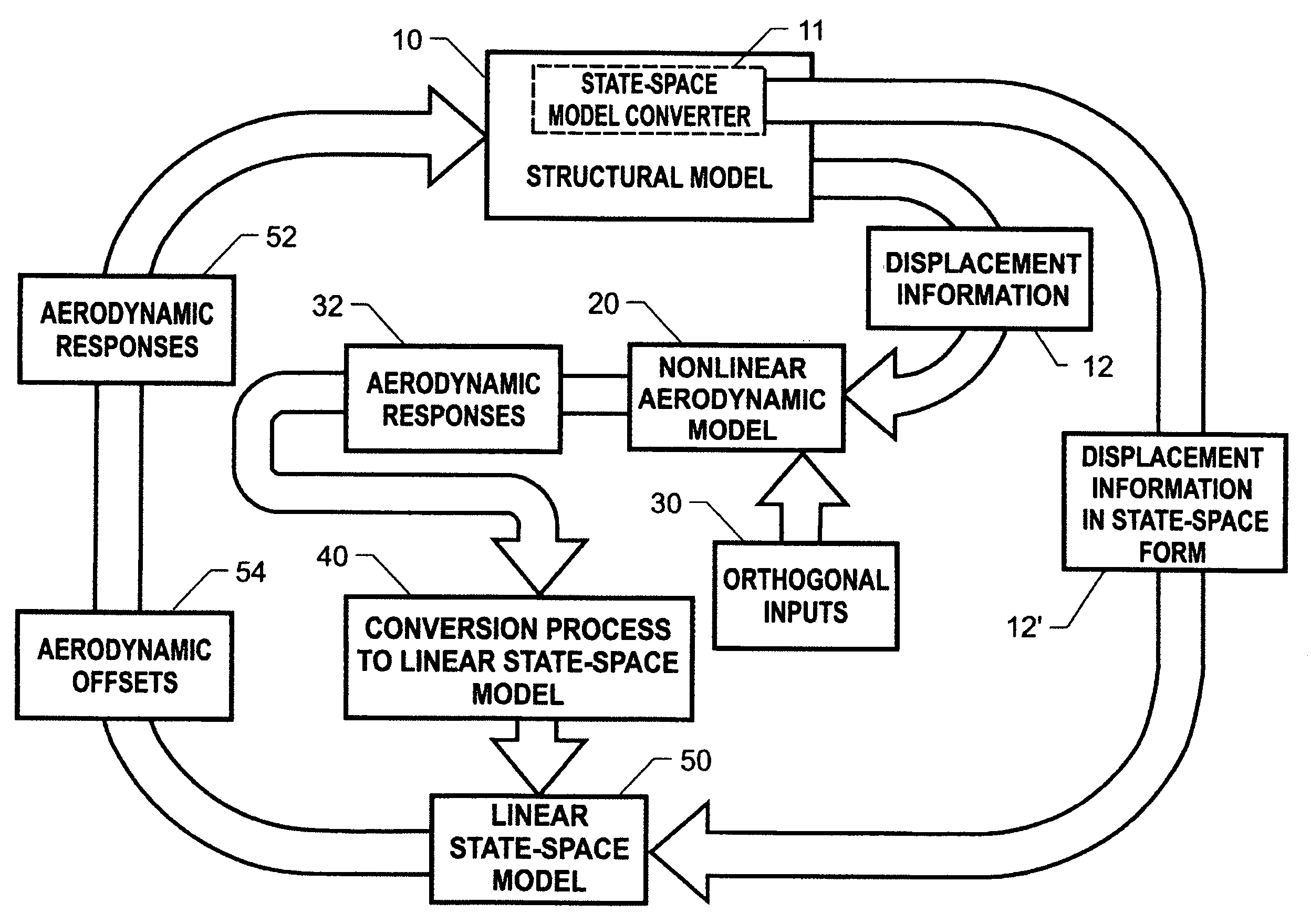
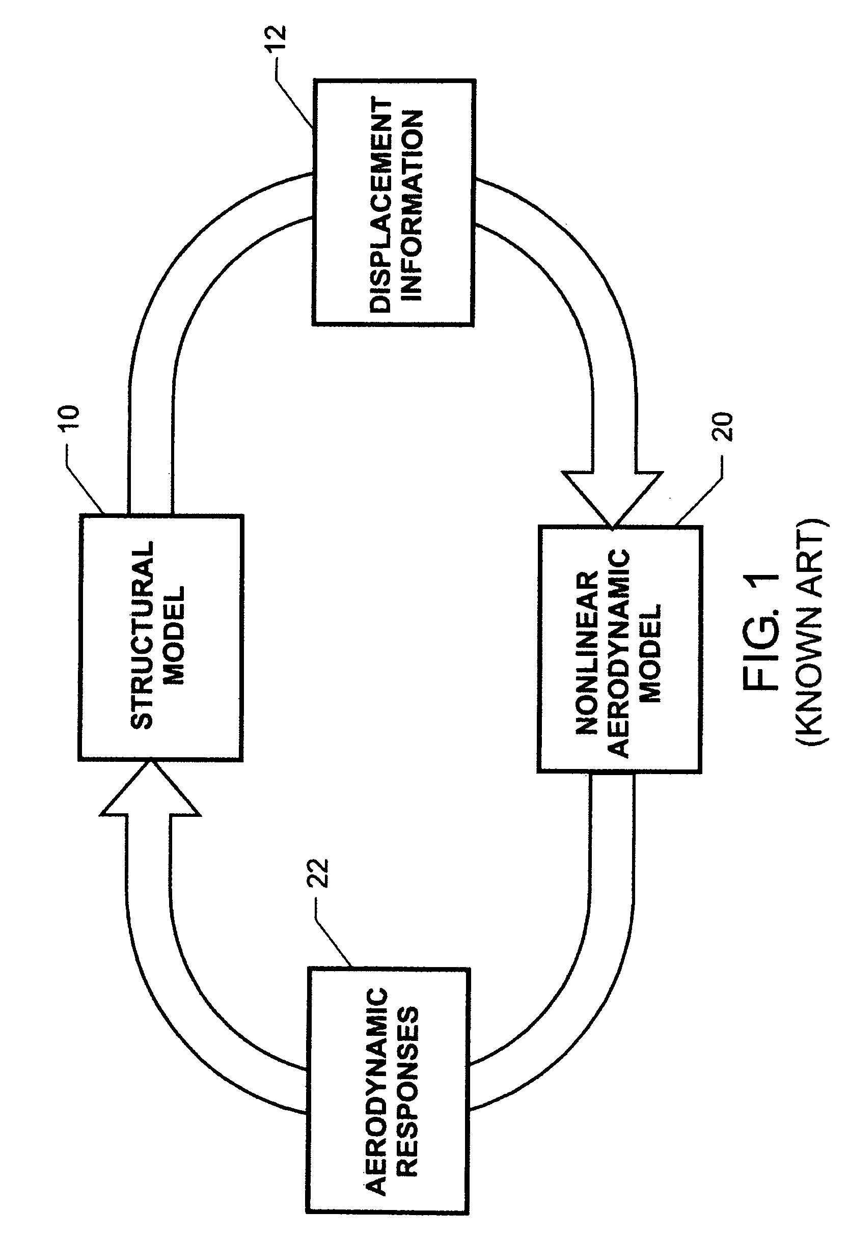
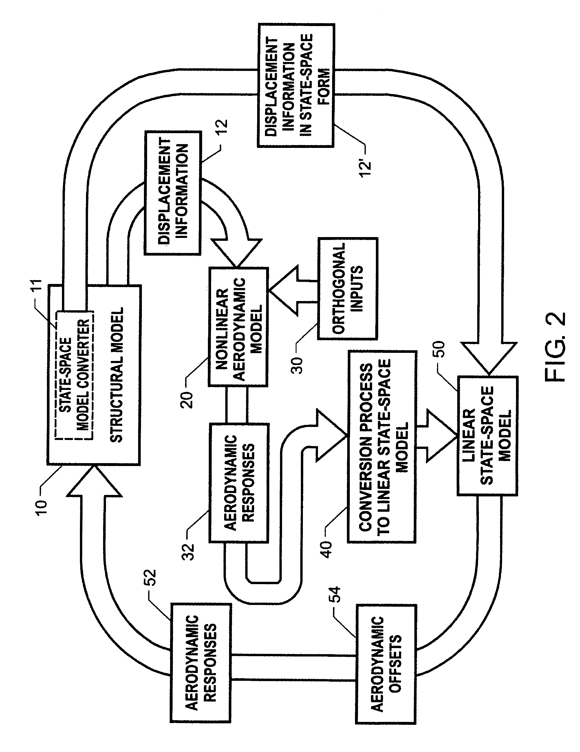
[0021]Referring again to the drawings and more particularly to FIG. 2, a method of performing computational aeroelastic analyses in accordance with an embodiment of the present invention is illustrated graphically. The attributes of this novel method that are the same as the traditional method (FIG. 1) will be referred to using common reference numerals. This new method can be applied to any flexible structure that can be modeled in terms of its various structural modes or displacement characteristics. For example, the present invention can be used to perform computational aeroelastic analyses on a variety of flexible aerodynamic structures such as wings, fuselages, and tail components.

[0022]Similar to traditional computational aeroelastic analyses methods, the present invention uses a structural model 10 that is a mathematical model describing the various structural modes for a flexible structure of interest. More specifically, structural model 10 provides an aeroelastic model that...


PUM


Abstract

Computational aeroelastic analyses typically use a mathematical model for the structural modes of a flexible structure and a nonlinear aerodynamic model that can generate a plurality of unsteady aerodynamic responses based on the structural modes for conditions defining an aerodynamic condition of the flexible structure. In the present invention, a linear state-space model is generated using a single execution of the nonlinear aerodynamic model for all of the structural modes where a family of orthogonal functions is used as the inputs. Then, static and dynamic aeroelastic solutions are generated using computational interaction between the mathematical model and the linear state-space model for a plurality of periodic points in time.

Description

[0001]Pursuant to 35 U.S.C. §119, the benefit of priority from provisional application 60 / 908,769, with a filing date of Mar. 29, 2007, is claimed for this non-provisional application.ORIGIN OF THE INVENTION[0002]This invention was made by an employee of the United States Government and may be manufactured and used by or for the Government of the United States of America for governmental purposes without the payment of any royalties thereon or therefor.BACKGROUND OF THE INVENTION[0003]1. Field of the Invention[0004]This invention relates to computational aeroelastic analyses. More specifically, the invention is a method for performing computational aeroelastic analyses using linear state-space models.[0005]2. Description of the Related Art[0006]When designing aerodynamic structures, it is important to understand if and under what aerodynamic conditions the structure will be stable and unstable. This is especially true if a structure is inherently flexible (e.g., a wing) such that un...

Claims


Application Information

Patent Timeline
IPC IPC(8): G06F17/50
CPCG06F17/5018G06F2217/16G06F30/23G06F2111/10
Inventor SILVA, WALTER A.
Owner NASA
Why Eureka
Try Eureka