Vacuum insulated glass building component and method and apparatus for its manufacture

Inactive Publication Date: 2008-10-09
GRENZEBACH MASCHINENBAU GMBH
View PDF18 Cites 46 Cited by
  • Summary
  • Abstract
  • Description
  • Claims
  • Application Information

AI Technical Summary

Benefits of technology

[0013]Since in the arrangement according to the present invention, the two individual panes are provided at their edges each with a metal foil strip and the metal foil strips of the two individual panes are welded together, a durably vacuum-tight connection between the individual panes is established which however is not rigid but which can accommodate relative thermal expansions of the two individual panes. Such expansion movements are accommodated, without tensions, by the metal foil strips which are interconnected by welding. In this way, a vacuum-tight non-rigid edge connection of the two individual panes of the vacuum-insulated glass building element is provided which, during use, remains essentially free from mechanical stresses also when the individual panes are subjected to high temperature differences. For such an arrangement also a reliable long life for the edge connection can be considered to be no problem and the formation of cracks as a result of thermal effects on the panes which could lead to a loss of the vacuum between the panes is avoided.
[0014]As essential advantages of the arrangement according to the invention, not only a predictably long life of the vacuum-insulated glass panel according to the invention is obtained in this way, but also a limitation of the panel to small formats is eliminated as it exists in connection with the rigid edge connections of conventional vacuum-insulated glass panels obtained by glass-welding of the two individual panes.
[0015]The glass panes can be joined along their edges with the metal foil strips either with the aid of glass solder by melt welding or by “cold” welding by means of ultrasound. In this connection, ultrasound welding is preferred since it causes no thermal stresses. In addition, the ultrasound welding procedure is simpler than the melt welding with glass solder.
[0016]This results in a further substantial advantage of the vacuum-insulated glass building element according to the invention in that the ultrasound welding causes no thermal stresses, and does not detrimentally affect the glass panes. If one of the glass panes consists of safety glass, the glass pane is not de-tempered by the effects of heat and the safety glass structure remains unchanged. In addition, highly effective low-emission coatings can be used which are not affected by the manufacture of the edge joint so that very high heat insulation values are obtained for the vacuum insulated building element.

Problems solved by technology

This long period of evacuation at high temperature does not only result in an expensive manufacturing process for the vacuum glass but also detrimentally affects the product quality.
However, because of the high temperatures used during evacuation over a long period, highly effective coatings with a low emission degree (soft coatings) cannot be used.
In addition, a high-temperature of about 450° C. maintained during evacuation over a period of about 2 hours results in the de-tempering of single pane safety glass so that it substantially loses its safety glass property.
As a result, the problem that none of the effective coatings for achieving low degrees of emission can be used and safety glass single panes are also in this case de-tempered.
However, whether the two single panes are welded together in an atmospheric chamber with subsequent evacuation of the intermediate space or in a vacuum chamber, in connection with conventional vacuum-insulated glass panels, there is always the substantial problem that the composite rigid glass panel formed by the welding of the individual panes will not withstand the stresses to which it is subjected during use: The two individual panes separated by the evacuated intermediate space during use assume different temperatures since the glass pane facing the room is warm and the pane facing the outside air is cooler, wherein the use of a coating for the reduction of heat losses by radiation increases that temperature difference substantially.
The temperature difference between the individual panes generated in this way results in substantial mechanical tensions.
This means that conventional vacuum-insulated glass panels are limited in size to certain maximum formats.
In addition, no reliable information is available concerning vacuum insulation glass panels used under conditions where they are subjected to high mechanical tensions.

Method used


Image

  • Vacuum insulated glass building component and method and apparatus for its manufacture
  • Vacuum insulated glass building component and method and apparatus for its manufacture
  • Vacuum insulated glass building component and method and apparatus for its manufacture

Examples


Embodiment Construction

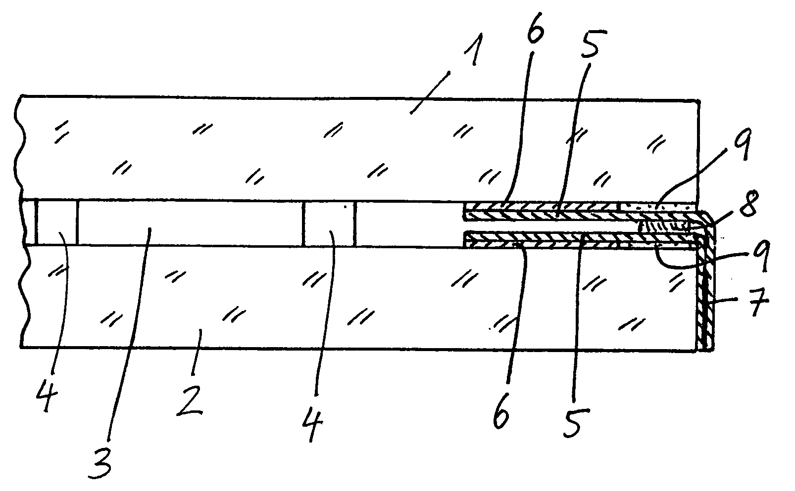
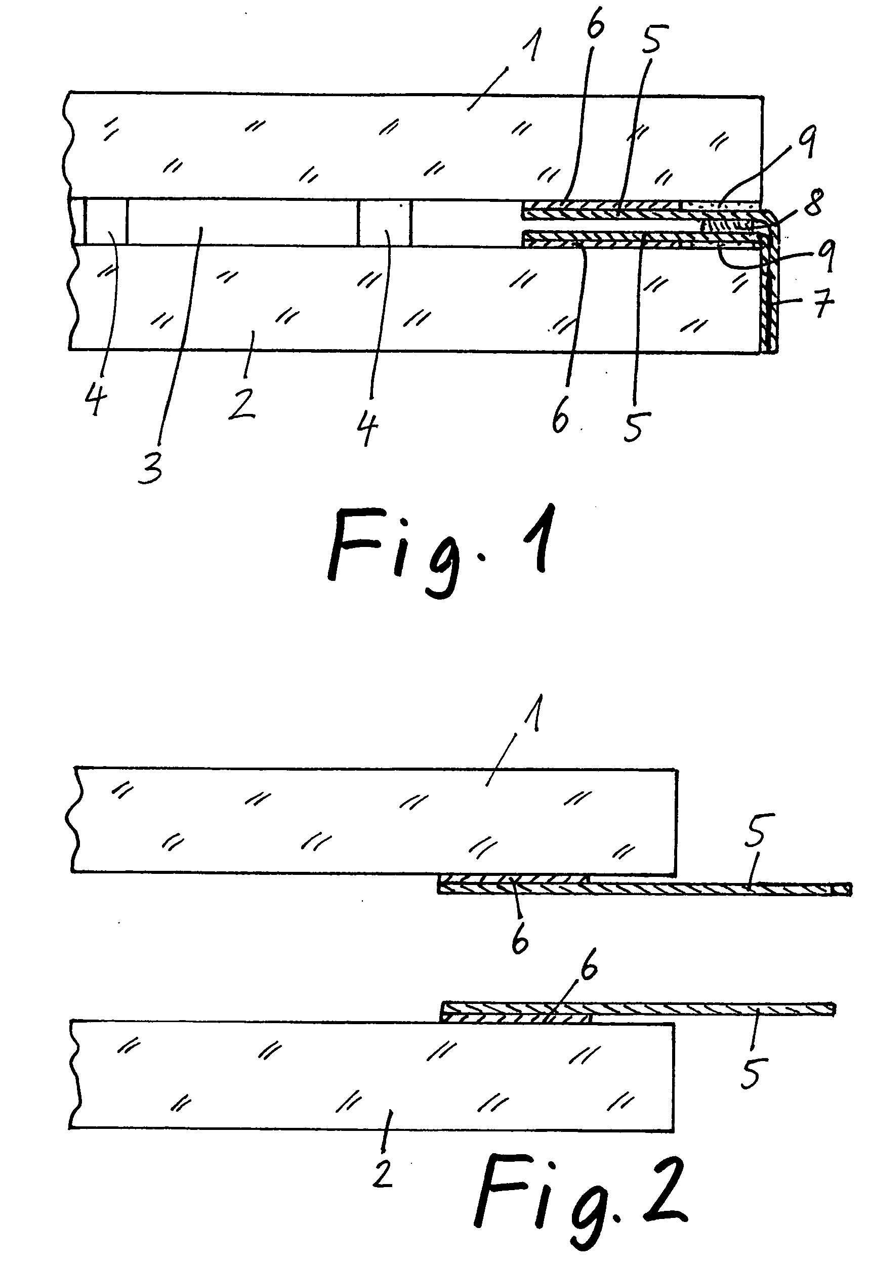
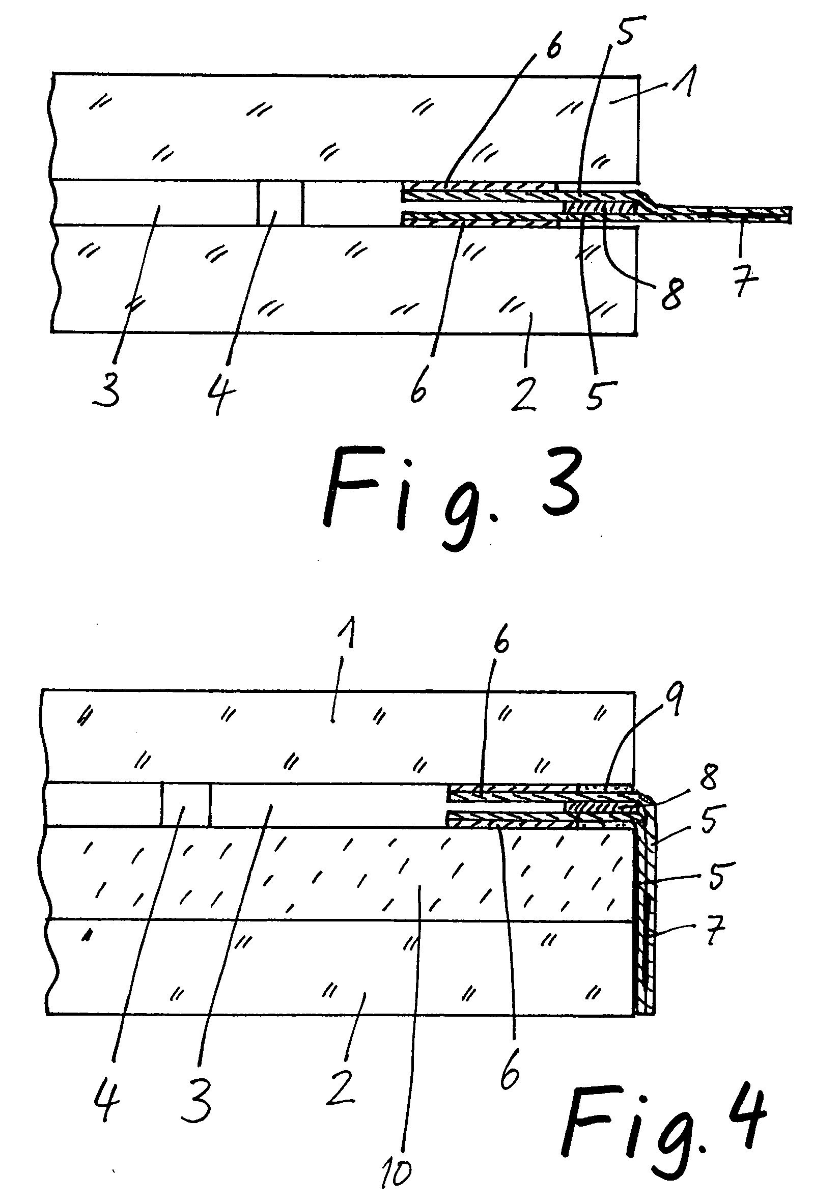
[0028]FIG. 1 shows, in cross-section, the edge area of a vacuum insulated glass building element in the form of a vacuum insulated glass panel with a finished edge connection. The arrangement comprises a cover pane 1 (outer pane) and a bottom pane 2 (inner pane), which are separated from each other by an intermediate pane space 3. In the intermediate pane space 3, there is a vacuum. The two panes 1 and 2 are held at a predetermined distance from each other by spacers 4 which are fixed to the bottom pane 2 in a grid-like pattern for example by cementing and on which the cover pane 1 is supported. The spacers may be small glass cylinders as shown but they may also be in the form of balls and they may also consist of metal.

[0029]The cover pane 1 and the bottom pane 2 each may have a thickness of 4 mm and the intermediate space 3 may have a thickness which is preferably in the range of 0.7 mm to 1 mm.

[0030]At the edge of each of the two panes 1, 2, a metal foil strip 5 is attached in a ...


PUM


Abstract

In a vacuum-insulated glass building component comprising first and second glass panes which are supported with respect to each other by spacers and are closed along their edges by a vacuum-tight edge connection so as to enclose between them a thin evacuated intermediate space, the edge connection is formed by first and second metal foil strips which are connected to the edge areas of the first and, respectively, second glass panes in a vacuum tight manner and the areas of the first and second metal foil strips projecting beyond the edges of the respective glass panes are welded together to join the glass panes.

Description

BACKGROUND OF THE INVENTION[0001]The invention relates to a vacuum-insulated glass building element that is to a vacuum-insulated glass pane and also to other building components consisting of a combination of vacuum insulated glass including for example a solar module. The invention also resides in a method and an apparatus for the manufacture of such vacuum-insulated building elements.[0002]A building element of the type with which the present invention is concerned comprises at least two glass panes or other areal glass structures with or without the inclusion of another areal body which are joined together with a thin evacuated space therebetween.[0003]Vacuum-insulated glass as such is known. It differs from conventional insulated glass in that the space between the panes is evacuated whereas, in conventional insulated glass, it is filled with a noble gas. Furthermore, the space between the glass panes of vacuum insulated glass is substantially thinner than in normal insulated g...

Claims


Application Information

Patent Timeline
IPC IPC(8): E04B1/74
CPCE06B3/6612E06B3/66304E06B3/6736E06B3/6775Y02B80/24Y02A30/249Y02B80/22
Inventor FRIEDL, WOLFGANG
Owner GRENZEBACH MASCHINENBAU GMBH
Why Eureka
Try Eureka