Control system for multiphase rotary machines

a control system and multi-phase technology, applied in the direction of motor/generator/converter stopper, dynamo-electric converter control, instruments, etc., can solve the problems of increasing the difficulty of performing sensorless control, affecting the accuracy of phase current measurement, etc., and achieve the effect of sufficient tim

Active Publication Date: 2008-10-09
DENSO CORP
View PDF10 Cites 27 Cited by
  • Summary
  • Abstract
  • Description
  • Claims
  • Application Information

AI Technical Summary

Benefits of technology

[0018]In the one aspect of the present invention, a line-to-line voltage between the first and second phase windings is represented by the amount of change in the line-to-line current. For this reason, the zero crossing of the line-to-line current and that of the amount of change in the line-to-line current include information indicative of a relationship between the line-to-line current and the line-to-line voltage. The inventors of this application have focused on the fact set forth above. Specifically, the one aspect of the present invention is to determine the command voltage value for the alternating current voltage to be applied to the multiphase windings based on the detected zero crossing of the line-to-line current and the detected zero crossing of the amount of change in the line-to-line current. This allows control of rotation of the multiphase rotary machine.
[0019]In particular, the line-to-line current has a difference in phase with respect to each of the first phase current and the second phase current. For this reason, using the phase difference between the line-to-line current and each of the first and second phase currents can ensure sufficient time required for each of the first and second zero crossing detectors to detect the corresponding zero closing. For this reason, it is possible to reliably control rotation of the multiphase rotary machine independently of the modulation factor.

Problems solved by technology

This reduces periods during which the phase current to flow each of the three-phase windings can be measured as a modulation factor of the sinusoidal PWM voltage increases, causing the measurement of the phase current to become difficult.
For this reason, the more the modulation factor of the sinusoidal PWM voltage increases, the more the difficulty of performing the sensorless control may increase.

Method used


Image

  • Control system for multiphase rotary machines
  • Control system for multiphase rotary machines
  • Control system for multiphase rotary machines

Examples


first embodiment

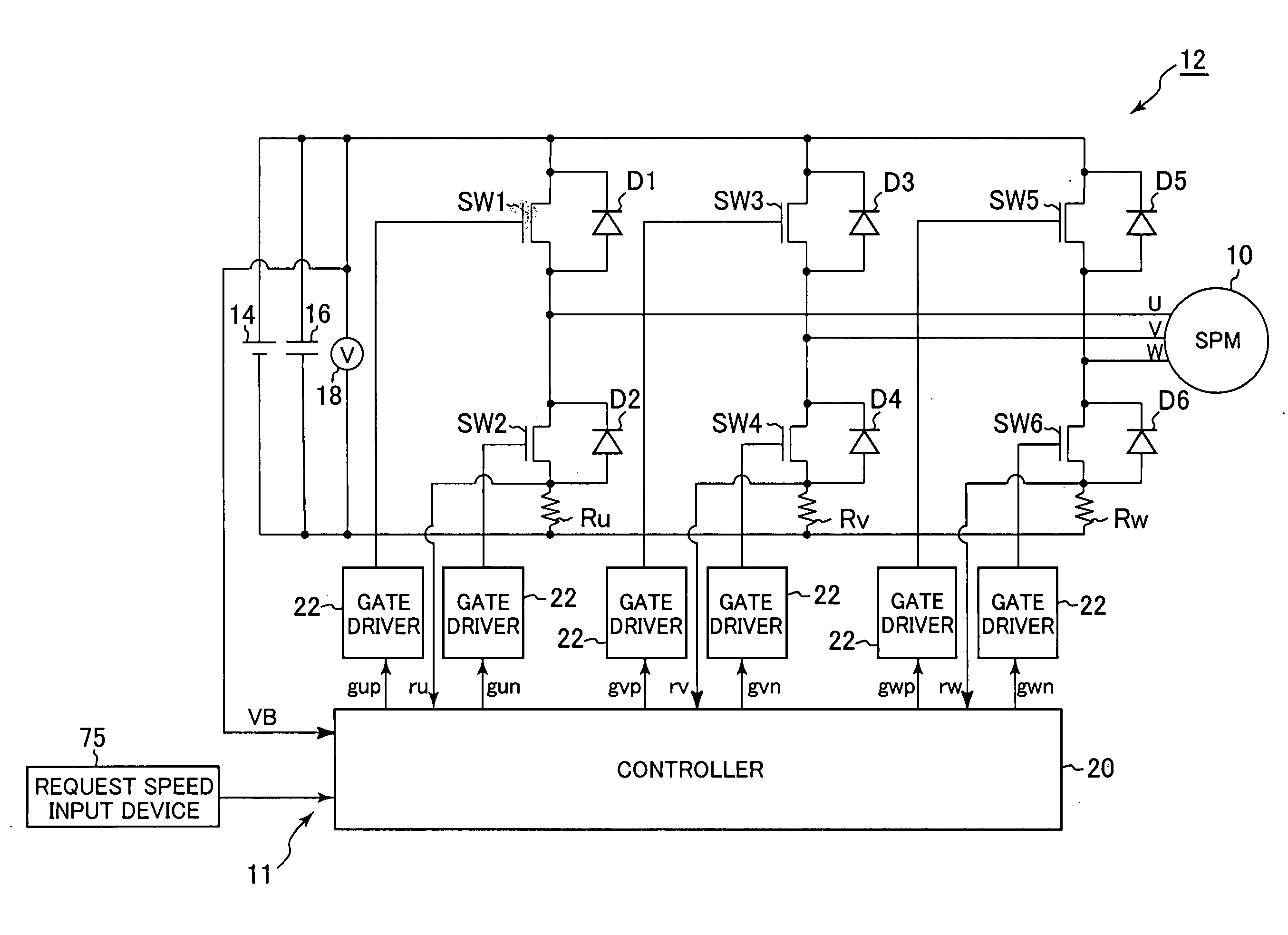
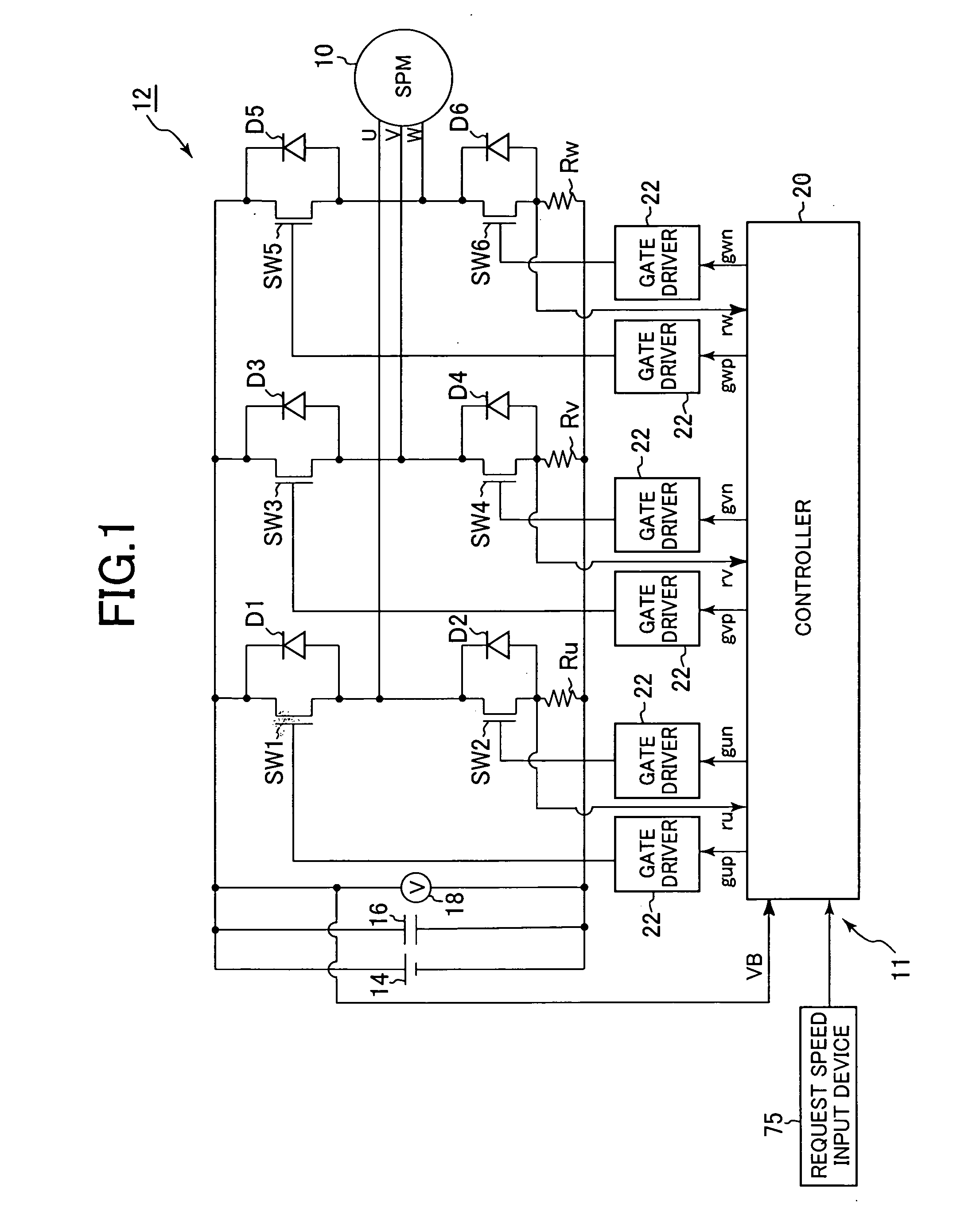
[0077]Referring to the drawings, particularly to FIG. 1, there is illustrated an interior magnet synchronous motor, referred to simply as “motor”10, and a control system 11 for controlling the motor 10. The motor 10 serves as, for instance, a blower motor of the in-vehicle air conditioner.

[0078]For example, the motor 10 is provided with an annular rotor having a rotor core. The rotor core of the rotor is provided at its circumferential portion with at least one N and S pole pair (see FIG. 7B).

[0079]The stator includes a stator core with, for example, an annular shape in its lateral cross section. The stator core is disposed around the outer periphery of the rotor core such that the inner periphery of the stator core is opposite to the outer periphery of the rotor core with a predetermined air gap.

[0080]The stator core also has a plurality of slots. The slots are formed through the stator core and are circumferentially arranged at given intervals. The stator also includes a set of th...

second embodiment

[0220]A control system for a motor according to a second embodiment of the present invention will be described hereinafter. The structure of the control system is substantially identical to that of the control system 11 according to the first embodiment except for some differences described hereinafter.

[0221]Thus, like reference characters are assigned to like parts in the control systems according to the first and second embodiments, and therefore, descriptions of the structure of control system, except for some differences, according to the second embodiment are simplified or omitted.

[0222]The control system according to the second embodiment is specially designed to adjust, in place of the phase φ, the electrical angular rate ω or ωd of the rotor each of the command voltages Vuc1, Vvc1, and Vwc1 based on the temporal difference ΔΦ of the phase of a target line-to-line current at the zero crossing Φ(I=0) with respect to the phase of polarity inversion of the amount of change in th...

third embodiment

[0233]A control system for a motor according to a third embodiment of the present invention will be described hereinafter. The structure of the control system is substantially identical to that of the control system 11 according to the first embodiment except for some differences described hereinafter.

[0234]Thus, like reference characters are assigned to like parts in the control systems according to the first and third embodiments, and therefore, descriptions of the structure of control system, except for some differences, according to the third embodiment are simplified or omitted.

[0235]The control system according to the third embodiment is specially designed to adjust, in place of the phase φ, the amplitude Vm of each of the command voltages Vuc1, Vvc1, and Vwc1 based on the temporal difference ΔΦ of the phase of a target line-to-line current at the zero crossing Φ(I=0) with respect to the phase of polarity inversion of the amount of change in the target line-to-line current at ...


PUM


Abstract

A control system aims at converting, via a switching circuit, a direct current voltage into an alternating current voltage to be applied to multiphase windings of a multiphase rotary machine to thereby control rotation of the multiphase rotary machine. In the control system, a command voltage determiner determines a command voltage value for an alternating current voltage to be applied to the multiphase windings based on a zero crossing of a line-to-line current and a zero crossing of the amount of change in the line-to-line current. A driving unit drives the switching circuit on and off based on the determined command voltage value to thereby modulate the direct current voltage to the alternating current voltage to be applied to the multiphase windings.

Description

CROSS REFERENCE TO RELATED APPLICATIONS[0001]This application is based on Japanese Patent Applications 2007-99163 and 2007-307309 filed on Apr. 5, 2007 and Nov. 28, 2007, respectively. This application claims the benefit of priority from the Japanese Patent Applications, so that the descriptions of which are all incorporated herein by reference.FIELD OF THE INVENTION[0002]The present invention relates to control systems for multiphase rotary machines, which are designed to control rotation of a rotor of a multiphase rotary machine without using sensors for measuring rotational positions of the rotor.BACKGROUND OF THE INVENTION[0003]Conventional control systems for multiphase rotary electric machines are designed to drive a plurality of switching elements connected to a multiphase rotary electric machine as a controlled object to thereby control rotation of the multiphase rotary electric machine.[0004]One example of such conventional control systems is disclosed in Japanese Patent Ap...

Claims


Application Information

Patent Timeline
Patent Type & Authority Applications(United States)
IPC IPC(8): H02P25/22
CPCH02M7/53873H02P23/0036H02P23/0004
Inventor AOKI, YASUAKIYOSHIDA, HIDEJI
Owner DENSO CORP
Why Eureka
Try Eureka