
MRI apparatus and control method therefor

a magnetic resonance imaging and apparatus technology, applied in the field of magnetic resonance imaging apparatus, can solve the problem of taking a long time to achieve imaging

Active Publication Date: 2008-10-09
GE MEDICAL SYST GLOBAL TECH CO LLC
View PDF24 Cites 1 Cited by
  • Summary
  • Abstract
  • Description
  • Claims
  • Application Information

AI Technical Summary

Benefits of technology

[0007]In a second aspect, the invention provides a version of the MRI apparatus according to the first aspect, characterized in that the scaling factor is the ratio between the sum of a plurality of factors, figured out for each of a plurality of images reconstructed as the root-mean square of pixel values on the basis of the data of the low frequency regions to which the substitute data have been added, and one factor out of those factors.
[0008]In a third aspect, the invention provides a version of the MRI apparatus according to the second aspect, characterized in that the one factor has been figured out of an image which, out of the plurality of images, derives from data collected in the SSFP pulse sequence in the first phase series.
[0009]In a fourth aspect, the invention provides a version of the MRI apparatus according to the first aspect, characterized in that in the low frequency regions, the matrix size in the central part, of the k-space having a matrix size of 256×256, is 64×256.
[0010]In a fifth aspect, the invention provides a version of the MRI apparatus according to the first aspect, characterized in that the plurality of phase series are four phase series.
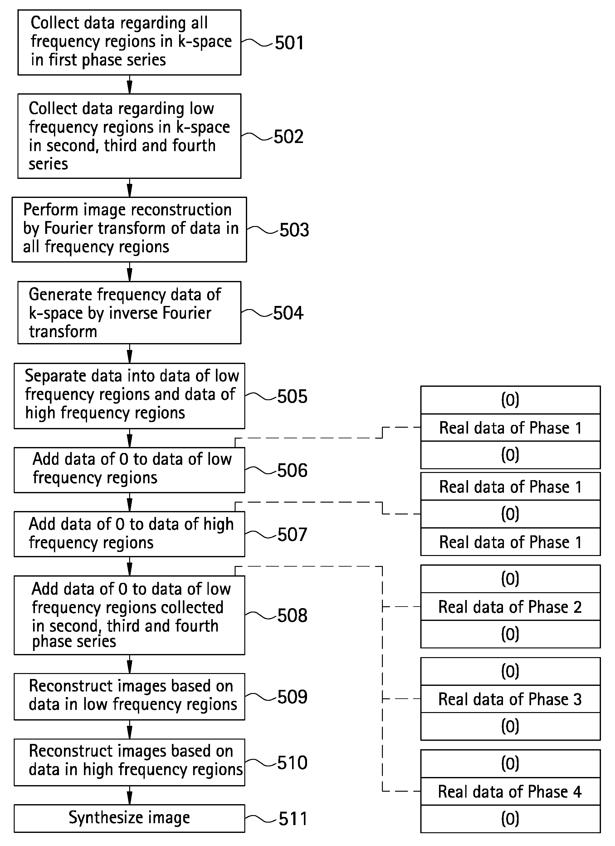
[0011]In a sixth aspect, the invention provides a method for controlling an MRI apparatus which performs MR imaging in an SSFP pulse sequence in which RF excitation is accomplished by a phase cycling method, the MRI apparatus control method being characterized in that the MRI apparatus is caused to collect data regarding all the frequency regions in a k-space in an SSFP pulse sequence in a first phase series out of a plurality of phase series; to collect data regarding low frequency regions in the k-space in the SSFP pulse sequence in the remaining phase series out of the plurality of phase series; to reconstruct an image by Fourier transform of the data regarding all the frequency regions collected in the SSFP pulse sequence in the first phase series; to generate frequency data of the k-space by inverse Fourier transform of the image; to separate the frequency data into data of the low frequency regions in the k-space and data of high frequency regions; to add data whose value is 0 to the separated data of the low frequency regions as substitute for the data of the high frequency regions; to add data whose value is 0 to the separated data of the high frequency regions as substitute for the data of the low frequency regions; to add data whose value is 0 to the data of the low frequency regions collected in the SSFP pulse sequence in the remaining phase series as substitute for the data of the high frequency regions; to reconstruct low space frequency images based on the low frequency regions to which the substitute data have been added; to reconstruct high space frequency images based on the high frequency regions to which the substitute data have been added; and to totally add the low space frequency images and the high space frequency images multiplied by a scaling factor.
[0012]In a seventh aspect, the invention provides a version of the MRI apparatus control method according to the sixth aspect, characterized in that the scaling factor is the ratio between the sum of a plurality of factors, figured out for each of a plurality of images reconstructed as the root-mean square of pixel values on the basis of the data of the low frequency regions to which the substitute data have been added, and one factor out of those factors.
[0013]In an eighth aspect, the invention provides a version of the MRI apparatus control method according to the seventh aspect, characterized in that the one factor has been figured out of an image which, out of the plurality of images, derives from data collected in the SSFP pulse sequence in the first phase series.
[0014]In a ninth aspect, the invention provides a version of the MRI apparatus control method according to the sixth aspect, characterized in that, in the low frequency regions, the matrix size in the central part, of the k-space having a matrix size of 256×256, is 64×256.
[0015]In a 10th aspect, the invention provides a version of the MRI apparatus control method according to the sixth aspect, characterized in that the plurality of phase series are four phase series.

Problems solved by technology

The imaging method described above, since it requires repetition of data collection often as the number of phase step series, takes a long time to accomplish imaging.

Method used


Image

  • MRI apparatus and control method therefor
  • MRI apparatus and control method therefor
  • MRI apparatus and control method therefor

Examples


Embodiment Construction

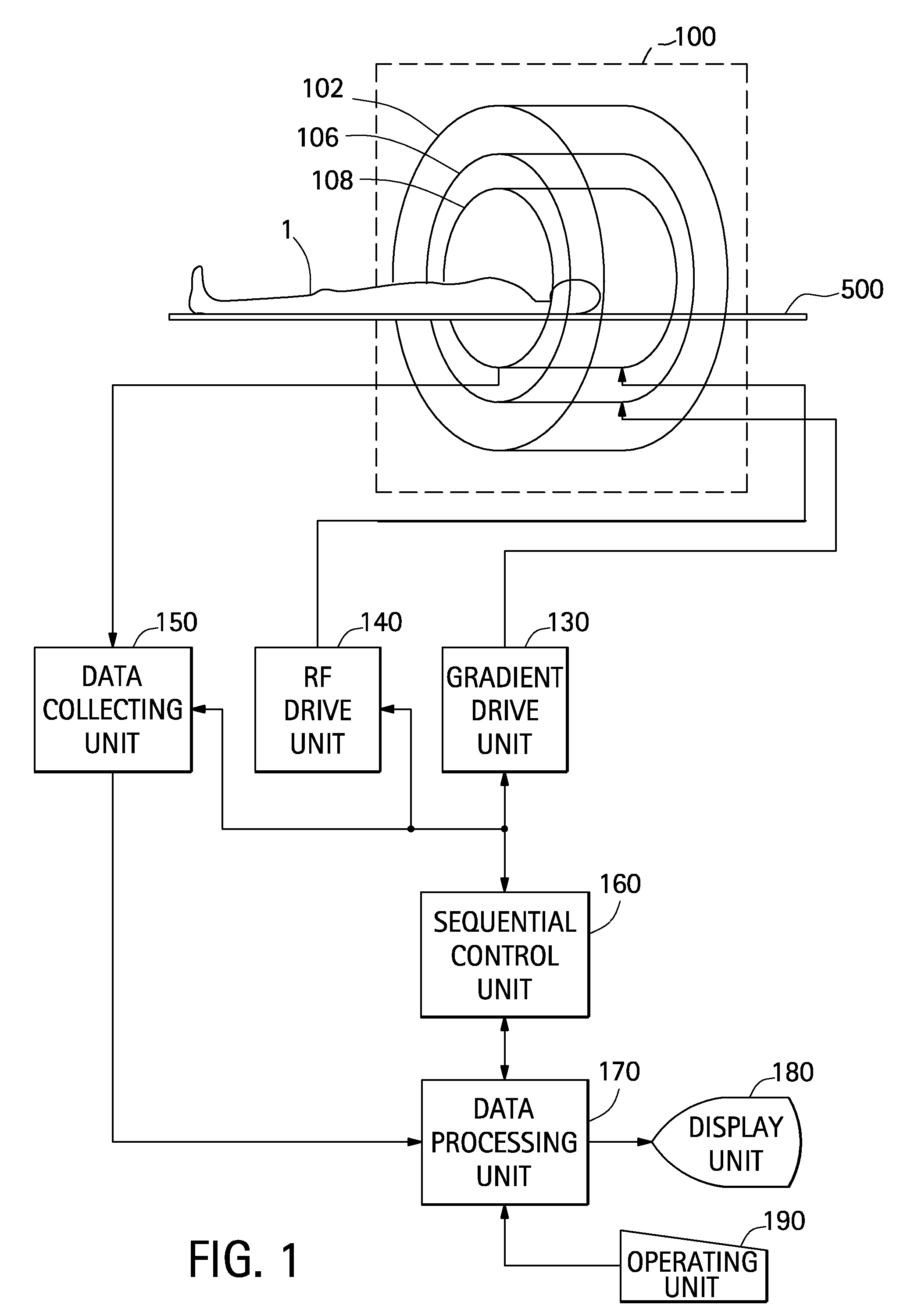
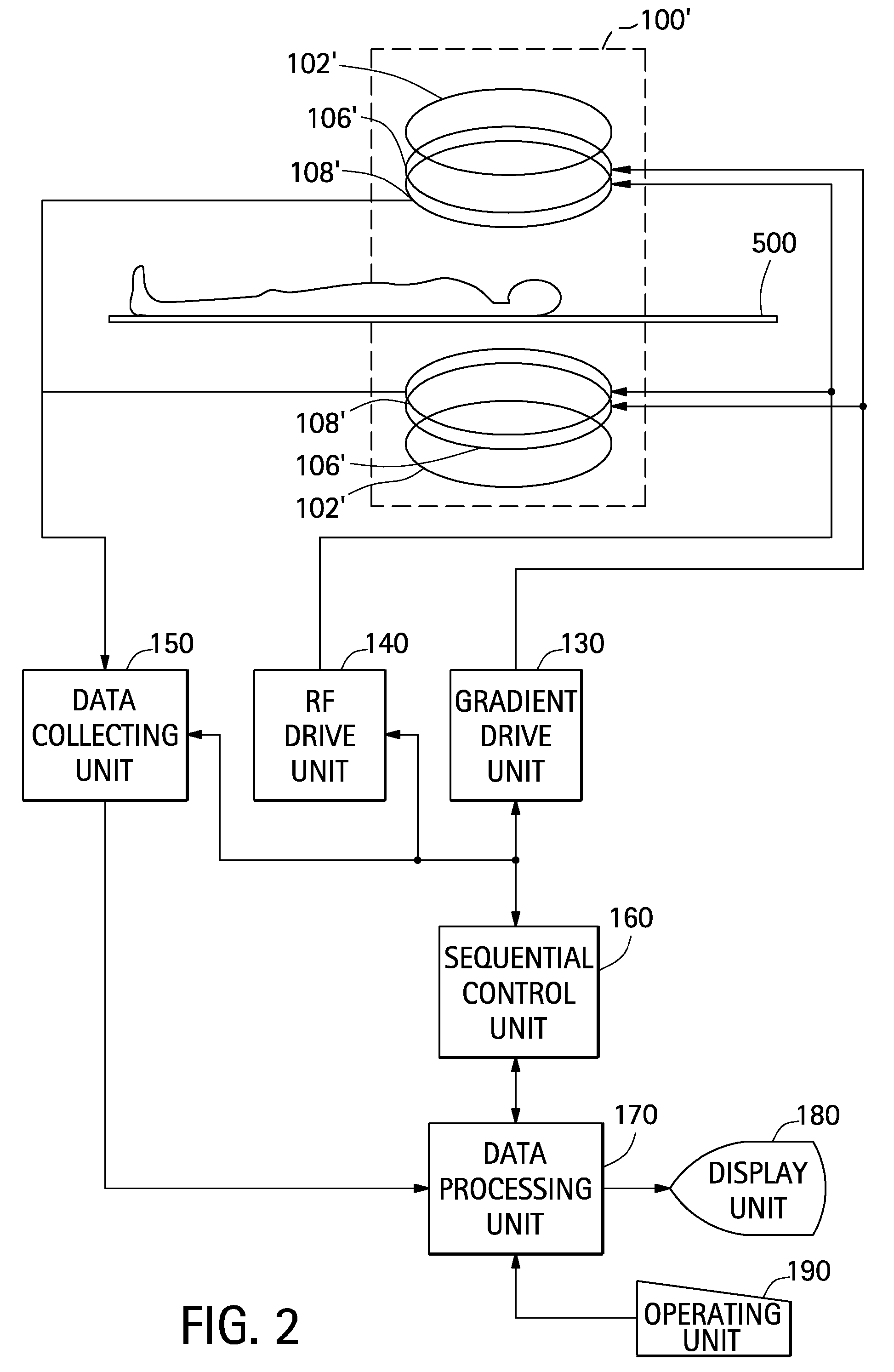
[0033]The best mode for carrying out the invention will be described in detail with reference to drawings. Incidentally, the invention is not limited to this best mode for carrying out the invention. A block diagram of an MRI apparatus is shown in FIG. 1. This apparatus is one example of the best mode for carrying out the invention. The configuration of this apparatus illustrates the best mode for carrying out the invention that relates to an MRI apparatus. The operation of this apparatus illustrates the best mode for carrying out the invention that relates to an MRI apparatus control method.

[0034]As shown in FIG. 1, this apparatus has a magnet system 100. The magnet system 100 has a main magnetic field coil unit 102, a gradient coil unit 106 and an RF coil unit 108. These coil units have substantially cylindrical shapes, and are arranged coaxially to one another. A subject 1, mounted on a cradle 500, is carried in and out by carriage means not shown into the substantially columnar ...


PUM


Abstract

An MRI apparatus which performs MR imaging in an SSFP pulse sequence in which RF excitation is accomplished by a phase cycling method is caused; to collect data regarding all the frequency regions in a k-space in an SSFP pulse sequence in a first phase series out of a plurality of phase series; to collect data regarding low frequency regions in the k-space in the SSFP pulse sequence in the remaining phase series out of the plurality of phase series; to reconstruct an image by Fourier transform of the data regarding all the frequency regions collected in the SSFP pulse sequence in said first phase series; to generate frequency data of the k-space by inverse Fourier transform of said image; to separate said frequency data into data of the low frequency regions in the k-space and data of high frequency regions; to add data whose value is 0 to said separated data of the low frequency regions as substitute for the data of the high frequency regions; to add data whose value is 0 to said separated data of the high frequency regions as substitute for the data of the low frequency regions; to add data whose value is 0 to the data of the low frequency regions collected in the SSFP pulse sequence in the remaining phase series as substitute for the data of the high frequency regions; to reconstruct low space frequency images based on the low frequency regions to which said substitute data have been added; to reconstruct high space frequency images based on the high frequency regions to which said substitute data have been added; and to totally add said low space frequency images and said high space frequency images multiplied by a scaling factor.

Description

CROSS REFERENCE TO RELATED APPLICATIONS[0001]This application claims the benefit of Chinese Patent Application No. 200710137976.3 filed Apr. 6, 2007, which is hereby incorporated by reference in its entirety.BACKGROUND OF THE INVENTION[0002]The subject matter disclosed herein relates to an MRI (Magnetic Resonance Imaging) apparatus and a control method therefor, and more particularly to an MRI apparatus which performs MR imaging in an SSFP (Steady State Free Precession) pulse sequence in which RF (radio frequency) excitation is accomplished by a phase cycling method and a control method therefor.[0003]As one of the methods for performing MR imaging of a subject with an MRI apparatus, there is an imaging method using an SSFP pulse sequence in which RF excitation is accomplished by a phase cycling method. By this method, the SSFP pulse sequence is executed while varying the phase of RF excitation by a prescribed step per TR (repetition time). A plurality of series of phase steps are m...

Claims


Application Information

Patent Timeline
Patent Type & Authority Applications(United States)
IPC IPC(8): G01R33/54
CPCG01R33/5613G01R33/565G01R33/56554
Inventor LAI, YONGCHUAN
Owner GE MEDICAL SYST GLOBAL TECH CO LLC
Learn More