Demodulator for Amplitude-Modulated Signals

Active Publication Date: 2008-10-09
NXP BV
View PDF1 Cites 5 Cited by
  • Summary
  • Abstract
  • Description
  • Claims
  • Application Information

AI Technical Summary

Benefits of technology

[0017]It is furthermore advantageous if the coupling element comprises an impedance transformer arranged between the signal input and the first reference voltage, and a current source arranged between the signal input and the second reference voltage. In this case, ground can be used for the second reference voltage, and a current source that is connected to ground can be used. The current source here can be realized by a current mirror. In this way, a separate component for producing the second reference voltage can be saved. For the first reference voltage, moreover, a reference voltage already present on the chip can likewise be used. Usually, such sources must not be too heavily loaded, for which reason it is advantageous to decouple them via an impedance transformer. Decoupling can be effected better

Problems solved by technology

The demodulator circuit is therefore insensitive both to different modulation depths and to in

Method used


Image

  • Demodulator for Amplitude-Modulated Signals
  • Demodulator for Amplitude-Modulated Signals
  • Demodulator for Amplitude-Modulated Signals

Examples


Embodiment Construction

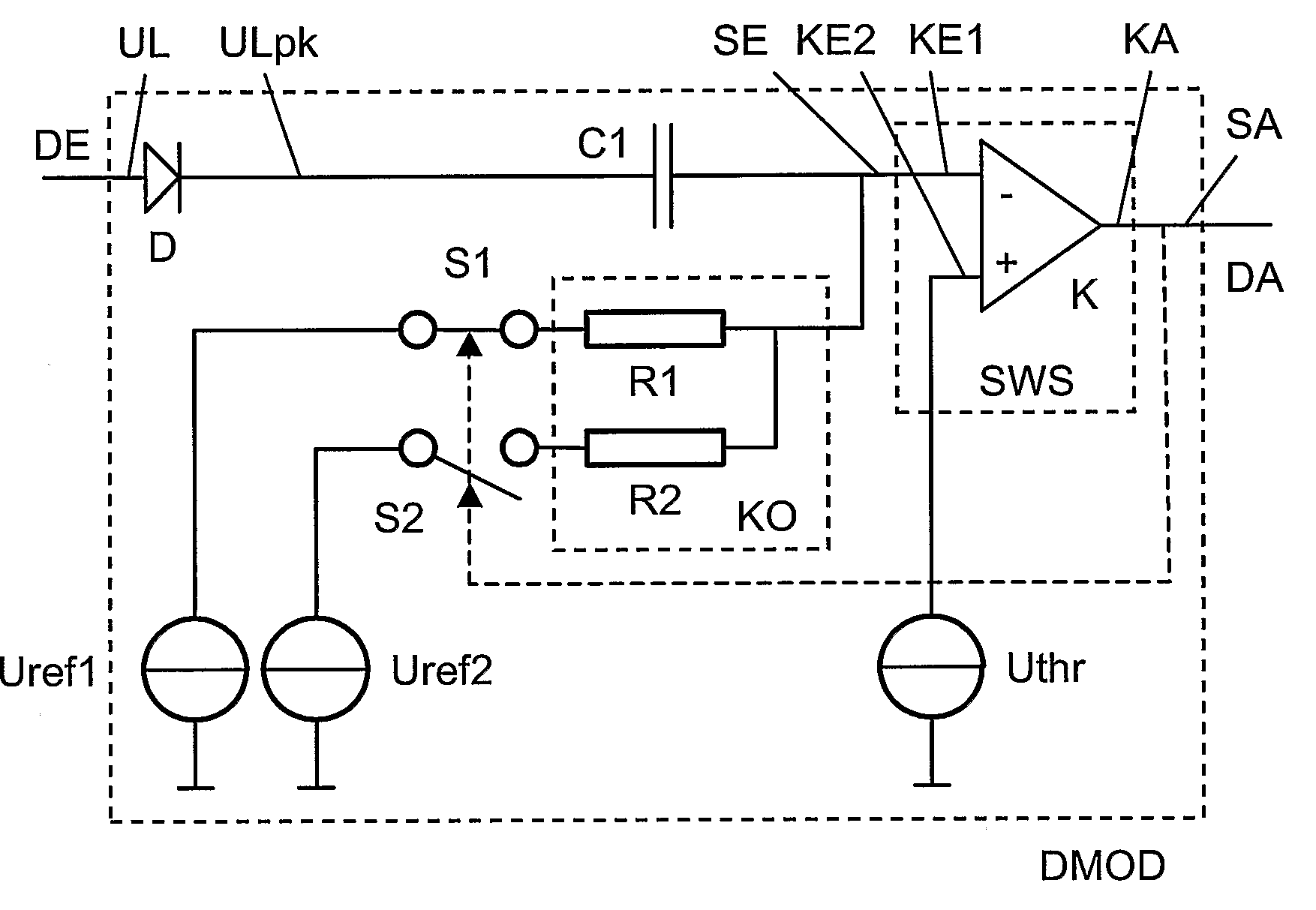
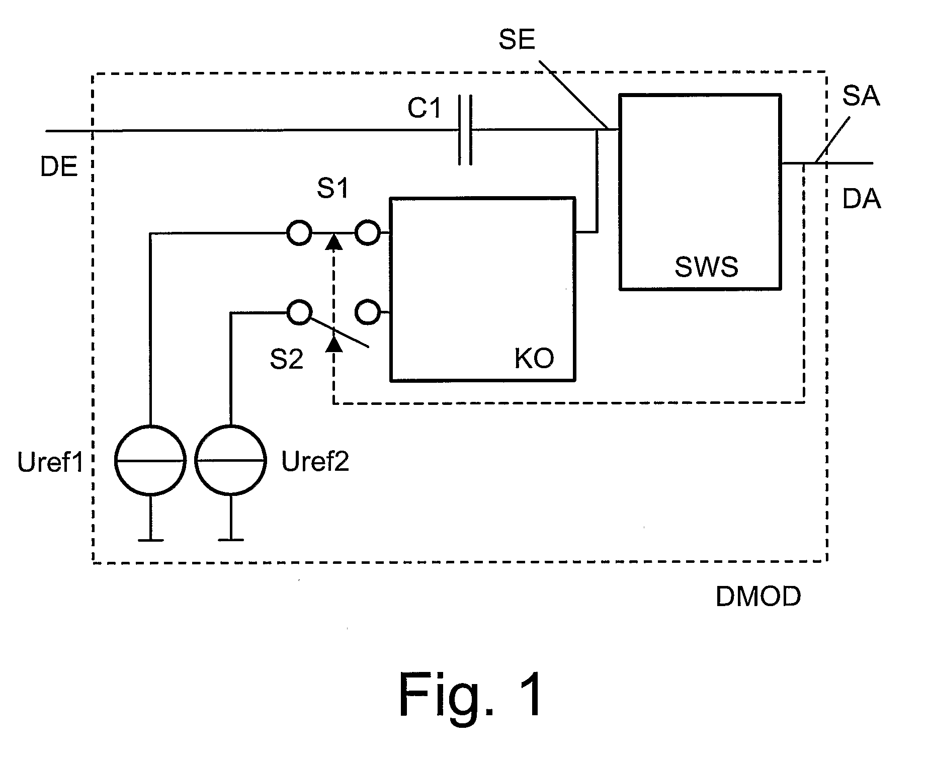
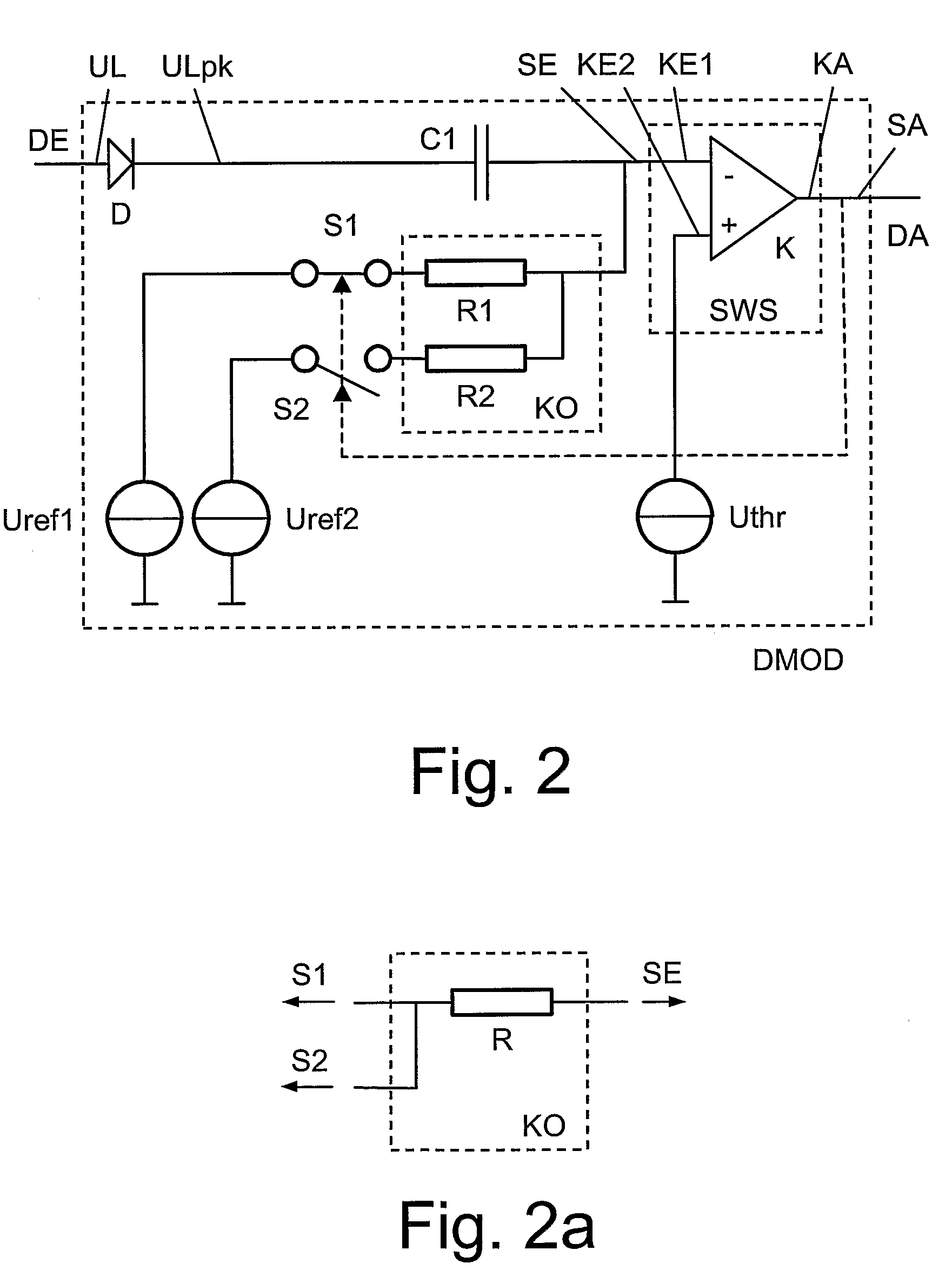
[0032]FIG. 1 shows a demodulator circuit DMOD in accordance with the invention, comprising a threshold switch module SWS, a first capacitor C1, a coupling element KO, a first and a second switch S1, S2, as well as a first and a second reference voltage Uref1, Uref2. A signal output SA of the threshold switch module SWS is connected to the output DA of the demodulator circuit DMOD. Furthermore, a signal input SE of the threshold switch module SWS is connected via the first capacitor C1 to the input DE of the demodulator circuit DMOD. Furthermore, the coupling element KO is connected to the signal input SE. The coupling element KO can furthermore be connected via the first switch S1 to the first reference voltage Uref1, or alternatively via the second switch S2 to the second reference voltage Uref2. Which switch is open and which is closed depends on the state of the signal output SA. Here, the first and second reference voltages Uref1 and Uref2 are to be selected such that one refere...


PUM


Abstract

A demodulator circuit (DMOD) for amplitude-modulated signals is defined which comprises a threshold switch module (SWS), wherein a signal output (SA) of the threshold switch module (SWS) is connected to the output (DA) of the demodulator circuit (DMOD) and a signal input (SE) of the threshold switch module (SWS) is connected via a first capacitor (C1) to the input (E) of the demodulator circuit (DMOD). In addition, the signal input (SE) can be connected via a coupling element (KO) to a first or alternatively a second

Description

FIELD OF THE INVENTION[0001]The invention relates to a demodulator circuit for amplitude-modulated signals, comprising a threshold switch module, wherein a signal output of the threshold switch module is connected to the output of the demodulator circuit.BACKGROUND OF THE INVENTION[0002]A demodulator circuit of the type named above is used for the demodulation of an amplitude-modulated signal emitted by a transmitter. One application are for example smart cards, in which a signal sent out by a so-called “reader” is received via a reception coil, and is subsequently evaluated by a demodulator circuit. In the course of this, high coil voltages must be reliably distinguished from low ones, and rising ones from falling ones.[0003]A possibility for effecting this, which is known from the prior art consists in comparing the voltage that is present at the reception coil with a reference voltage, using a comparator. A comparator is essentially an operational amplifier that is operated not i...

Claims


Application Information

Patent Timeline
IPC IPC(8): H03D1/00
CPCG06K7/0008G06K19/0723H03D1/10H04L25/061H04L27/06
Inventor KRANABENTER, HELMUT
Owner NXP BV
Why Eureka
Try Eureka