Miniature capacitive acoustic sensor with stress-relieved actively clamped diaphragm

a capacitive diaphragm, active clamping technology, applied in the field of capacitive microphones, can solve the problems of fundamental problems in the control of diaphragm material properties and the like, and achieve the effects of minimizing fabrication cost, maximizing fabrication yield, and minimizing fabrication complexity

Inactive Publication Date: 2008-10-09
NOVUSONIC CORP
View PDF8 Cites 47 Cited by
  • Summary
  • Abstract
  • Description
  • Claims
  • Application Information

AI Technical Summary

Benefits of technology

[0012]It is therefore an object of this invention to devise an acoustic sensor structure, in which the influence of the diaphragm intrinsic stress and stress eccentricity can be drastically reduced without the associated variation in microphone performance.
[0013]It is a further object of this invention to realize such an acoustic sensor structure, in which the diaphragm has a relieved intrinsic stress, while remaining flat without bow.
[0016]It is a further object of this invention to realize such an acoustic sensor structure with minimal fabrication complexity to minimize fabrication cost and to maximize the fabrication yield.

Problems solved by technology

While significant prior-art exists in the area of the design of acoustic sensors with stress-relieved or low-stress diaphragms, fundamental issues with diaphragm material properties and the control thereof remain.

Method used


Image

  • Miniature capacitive acoustic sensor with stress-relieved actively clamped diaphragm
  • Miniature capacitive acoustic sensor with stress-relieved actively clamped diaphragm
  • Miniature capacitive acoustic sensor with stress-relieved actively clamped diaphragm

Examples


Embodiment Construction

[0028]The present invention arises from the realization that the electrostatic attraction force, which is always present in a capacitive acoustic sensor structure, can be utilized in a specially designed structure to provide a clamping force of the diaphragm, which in turn can serve to flatten a diaphragm with intrinsic bow and provide for an effective acoustic seal between the diaphragm and the opposing clamping surface. A further important realization that applies to the present invention is that such a structure can be implemented using materials and fabrication processes that are entirely compatible with electronic circuit fabrication processes, such as CMOS, thereby allowing the fabrication of the acoustic sensor structure directly on substrates containing electronic circuitry.

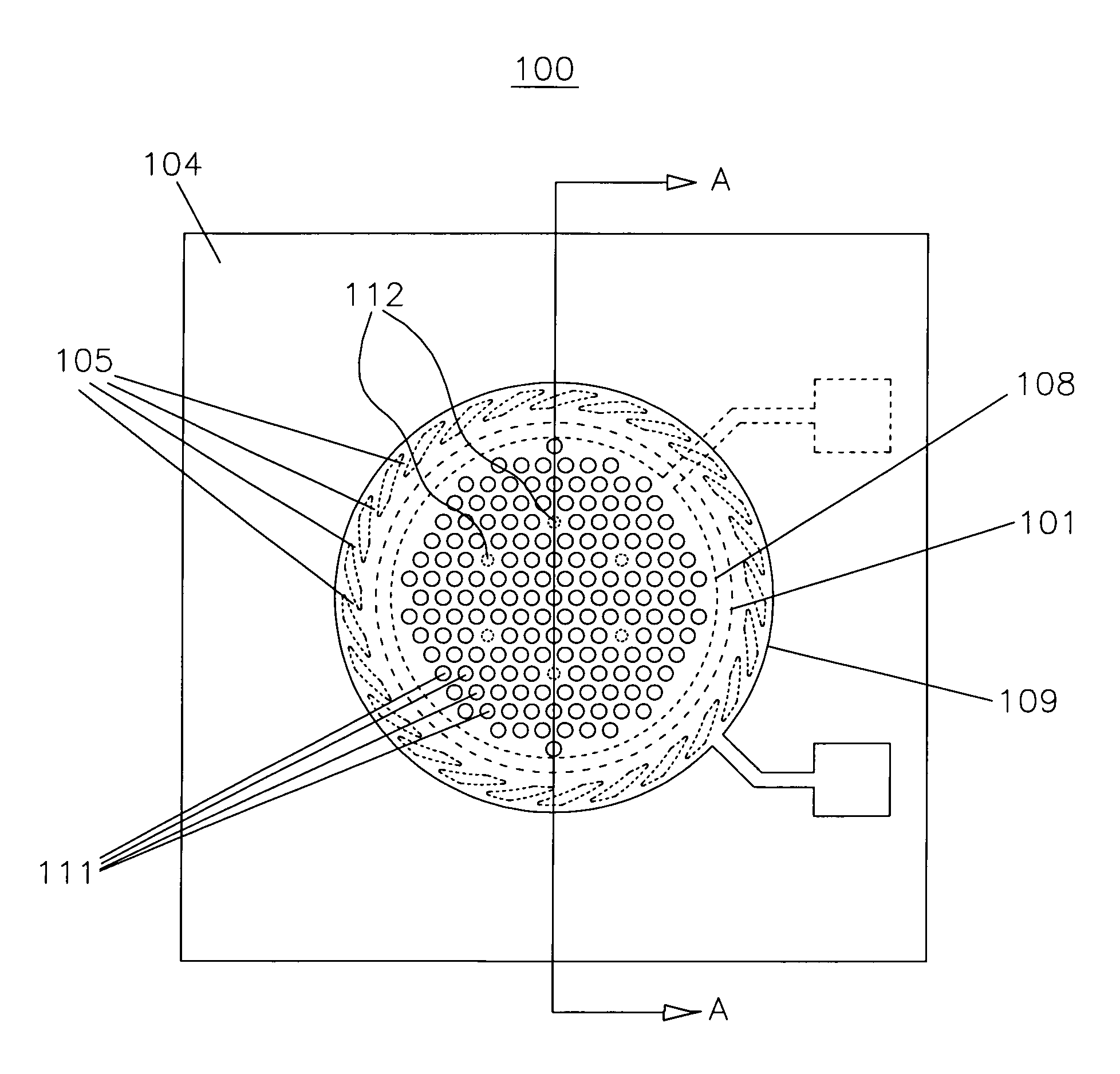
[0029]A preferred embodiment of the acoustic sensor 100 according to the present invention is shown in top view in FIG. 6, cross-sectional view in FIG. 7, and three-dimensional cut-away view in FIG. 8. Th...


PUM


Abstract

An acoustic sensor is disclosed which can be fabricated on a single chip with an electronic detection circuit by modular integration of the fabrication processes. An advantage of the disclosed acoustic sensor with on-chip signal detection circuit is smaller overall device size and lower sensitivity to electromagnetic interference and vibration. A second advantage of the disclosed acoustic sensor is the combined stress-relief and electrostatic clamping design of the diaphragm, which allows for further reduction of the diaphragm size, and hence device size, without compromising the microphone acoustic sensitivity, and at same time eliminates issues with diaphragm bow normally associated with stress-relief techniques.

Description

[0001]This application claims priority of U.S. provisional patent application No. 60 / 910,468 hereby incorporated by reference.FIELD OF THE INVENTION[0002]The invention relates to the fields of acoustic transducers and sensors. Specifically, it relates to the field of capacitive microphones made using micro machining (MEMS) fabrication processes.BACKGROUND OF THE INVENTION[0003]A number of important prior art inventions have been disclosed in which various design and fabrication methods are employed to achieve a stress reduction of the microphone diaphragm. A common issue in the fabrication of thin-film diaphragms using micro machining technology is the control and repeatability of the intrinsic stress in the thin film materials. As the intrinsic stress of the diaphragm strongly affects the acoustic compliance of the diaphragm, and hence the sensitivity of the microphone, there is therefore a direct relationship between the repeatability of the diaphragm intrinsic stress and the micr...

Claims


Application Information

Patent Timeline
Patent Type & Authority Applications(United States)
IPC IPC(8): H04R25/00
CPCH04R19/005H04R19/04H04R31/00
Inventor PEDERSEN, MICHAEL
Owner NOVUSONIC CORP
Why Eureka
Try Eureka