Polymer Emi Housing Comprising Conductive Fibre

a technology of conductive fibre and polymer emi, which is applied in the direction of shielding materials, ways, casings/cabinets/drawers of electrical apparatus, etc., can solve the problems of particularly difficult edges of the shell, and achieve the effect of improving shielding efficiency and efficient production

Inactive Publication Date: 2008-10-09
SABIC INNOVATIVE PLASTICS IP BV
View PDF12 Cites 10 Cited by
  • Summary
  • Abstract
  • Description
  • Claims
  • Application Information

AI Technical Summary

Benefits of technology

[0010]The main object of the invention is therefore to improve on the prior-art. As such the first object of the invention is to provide for an easy-to-produce housing that has an improved shielding efficiency compared to the existing art. A further object of the invention is to provide a housing that largely resolves the ‘contacting problem’. Moreover, the invention resolves this problem over a wide frequency range between 10 MHz and 10 GHz. It is a further object of the invention to provide a method for implementing such housing. Moreover the method provides an efficient way to produce the housing without the need of much additional work or materials.
[0013]The areas may coalesce to form one or more paths on the surface (dependent claim 2). These paths may be closed or not closed depending on the needs of the design. For example the conductive fibres at the edges of the shell may be uncovered. The edges of the shell are particularly difficult areas as explained before. Another area where uncovered fibres help to improve the shielding is at the rim of a feedthrough hole. Recesses of circular or rectangular or any other polygonal shape can define such a hole. The recesses can take the form of a continuous groove are can be segmented. As the recesses weaken the strength of the shell on these places, the shapes can be easily pushed through. In this way the conductive fibres are uncovered. The uncovered fibres can then, for example, electrically contact the shielding of a cable fed through the hole thus improving the overall shielding.
[0041]This mold is the negative of the shell to be formed. The mold is particular in that it defines specific protrusions and recesses on the shell, that on their turn define the areas on the surface of the shell where the conductive fibres will be uncovered. The mold must be so designed that it prevents or eliminates bubble formation in the shell, bubbles that could spoil the visual appearance and the strength of the shell.
[0042]The step of uncovering the fibres can be performed off-line after ejection and cooling down of the shell. More convenient is of course if the uncovering step occurs before or during ejection of the freshly made shell, as this eliminates the need for additional handling of the shell (dependent claim 17). The step of uncovering of the conductive fibres is preferably performed by breaking-off the protrusions or by breaking the shell at the predefined recesses (dependent claim 18). The protrusions as well as the recesses are so designed as to allow a clean breakage without burr, but with enough area uncovered to have a good joint. Recesses can be used to uncover the fibres at the edges. Or they can be used to form a push-through hole at a specific place. The uncovering step can either be done manually or by a robot. However, the operation of breakage is best introduced during the ejection of the shell. To this end injection-molding machines with double die pairs that can be independently moved relative to one another can be used.

Problems solved by technology

The edges of the shell are particularly difficult areas as explained before.

Method used


Image

  • Polymer Emi Housing Comprising Conductive Fibre
  • Polymer Emi Housing Comprising Conductive Fibre
  • Polymer Emi Housing Comprising Conductive Fibre

Examples


first embodiment

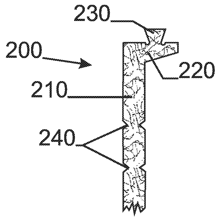
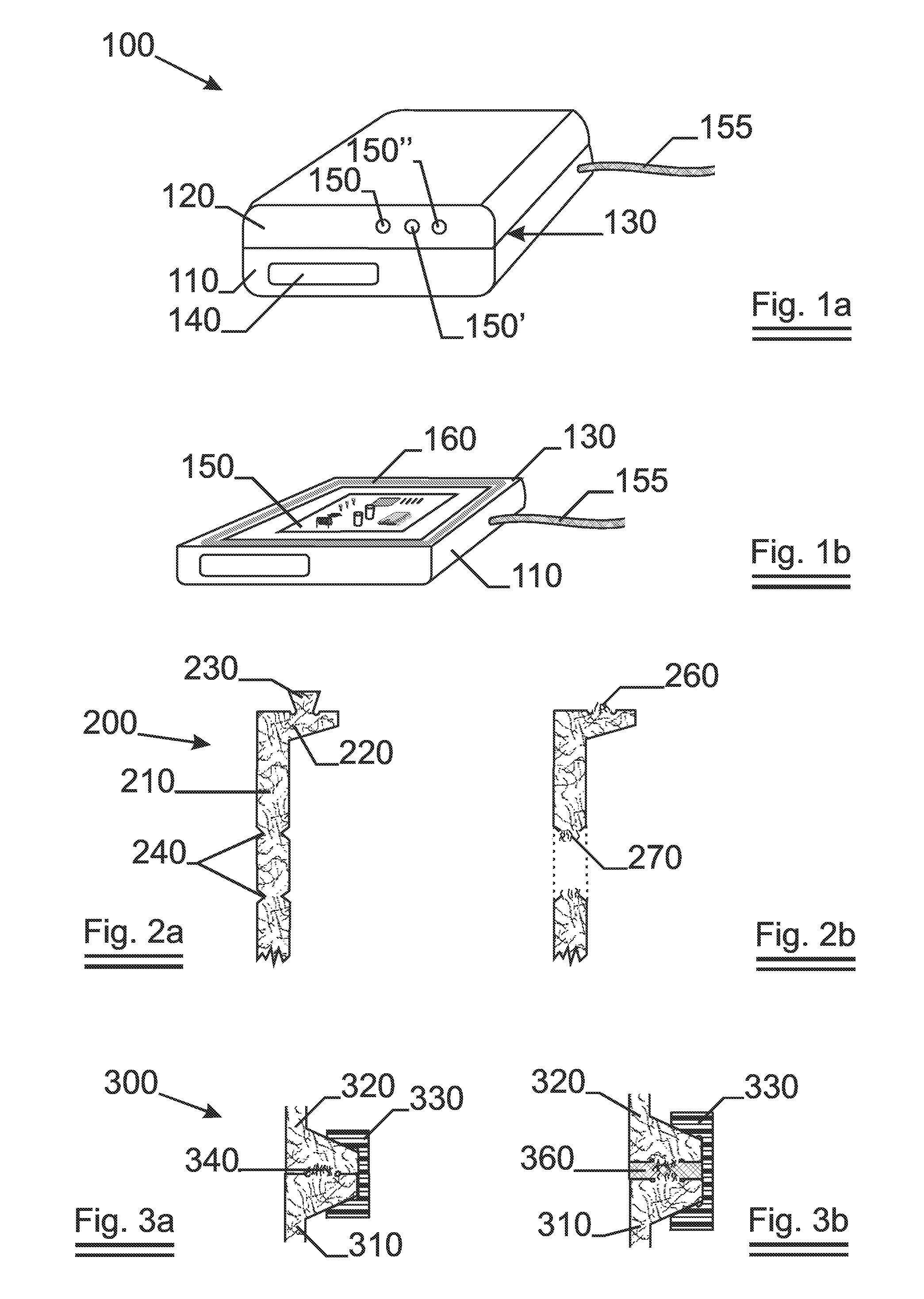
[0071]In a first embodiment granules containing 75% by weight stainless steel fibres (the remainder being 25% by weight polymer material). The stainless steel fibres have an equivalent diameter of 8 μm and are 5 mm long. The fibres were made from AISI302 type of stainless steel. These were mixed into a masterbatch with PC granules so as to obtain 3% of stainless steel fibre by volume in the finished shell. A shell—in the form of a half box like the one depicted in FIG. 1 but without apertures—was injection molded from this mixture under optimised conditions for injection pressure, back pressure, injection speed, temperature and other process parameters: a procedure known to the person skilled in the art. The width of the shell was 3 mm. In a first attempt to make a joint, an overlap between the edges of the shell was implemented: at the borders, the mold was such that the thickness of the shell halved at 5 mm from the edges. Matching the two pieces together formed the joint that was...

third embodiment

[0076]In a third embodiment, the results of which are represented in FIG. 8, a masterbatch was prepared by mixing fibre granules with PC and ABS polymer granules. The masterbatch contained 30% by weight stainless steel fibres of type AISI302 the remainder being the polyester jacket. Fibres have an equivalent diameter of 8 μm and a length of 5 mm. The volume concentration of fibres was raised to 6%. Again an overlap joint and a joint with uncovered fibres and a gasket were made and measured. Again the fibres were uncovered by breaking-off the lips. The results are shown in FIG. 8: 850 is the curve for an overlap and 860 is the curve for uncovered fibres in combination with the gasket. The influence of the increased fibre volume is obvious.

[0077]Besides the above three embodiments many others have been made and tested. With the other uncovering methods the following general results were obtained:[0078]Scraping-off the polymer rich layer at the edges of the shell yields results that ar...


PUM

PropertyMeasurementUnit
lengthaaaaaaaaaa
lengthaaaaaaaaaa
equivalent diameteraaaaaaaaaa

Abstract

An electromagnetic shielding housing is presented that is made up out of one or more shells. The shells comprise polymer and conductive fibres and have a polymer rich surface that covers the fibres except for predefined areas where the fibres are substantially uncovered. The conductive fibres can be metal-coated non-metallic fibres or plain metallic fibres, preferably plain stainless steel fibres. A method for uncovering the fibres is also presented which comprises the breaking-off of selected protrusions or the breaking of the shell at selected recesses so as to uncover the fibres. The housing and the method solve the problem that the polymer skin leads to inferior shielding at the joint of the shells.

Description

FIELD OF THE INVENTION[0001]The present invention relates to housings that abate electromagnetic interference (EMI) by absorbing or reflecting electromagnetic waves. The housings are assembled out of one or more shells that neatly match together. At least one of the shells is made from a polymer material wherein electrically conductive fibres are dispersed. The fibres are arranged such that contact between fibres of different shells is optimised. The invention is also extended to a method to produce such a shell.BACKGROUND OF THE INVENTION[0002]As the electromagnetic (EM) environment is more and more polluted with radiation of an ever increasing number of electronic appliances working at more and more dispersed frequencies, the need increases for housings that on the one hand keep the radiation emitted by an electronic device inside the housing while on the other hand prevent outside radiation to disturb the functioning of the device. This housing therefore must at least reflect the...

Claims


Application Information

Patent Timeline
Patent Type & Authority Applications(United States)
IPC IPC(8): H05K9/00B29C45/00
CPCH05K9/0015H05K9/0073Y10T428/24893Y10T428/24909Y10T428/1372Y10T428/24372H05K9/00H05K5/00
Inventor DEWITTE, RIKVERBRUGGE, WIMDE BONDT, STEFAANWILLEMS, PAUL ABRAHAMBROUNNE, ROBERT FRANS
Owner SABIC INNOVATIVE PLASTICS IP BV
Why Eureka
Try Eureka