Fuel Cell System

a fuel cell and system technology, applied in the direction of electrochemical generators, secondary cells servicing/maintenance, transportation and packaging, etc., can solve the problem of differential pressure between the electrodes, and achieve the effect of reliably starting up

Inactive Publication Date: 2008-10-09
HONDA MOTOR CO LTD
View PDF1 Cites 34 Cited by
  • Summary
  • Abstract
  • Description
  • Claims
  • Application Information

AI Technical Summary

Benefits of technology

[0014]The object of the present invention is to provide a fuel cell system able to startup reliably, even below the freezing point.
[0026]According to the present invention, the fuel cell system is provided with the auxiliary device electric power control means for Limiting electric power consumed by auxiliary device to startup a fuel cell based on the temperature of or around the electrical storage device. For example, when the temperature of the electrical storage device is below the freezing point, the auxiliary device is driven within the range of the electric power available in the electrical storage device, by limiting electric power consumed by the auxiliary device by the auxiliary device electric power control means so that the fuel cell system can be started up reliably.

Problems solved by technology

However, in such a fuel cell system, under a condition in which power generation is stopped by stopping the supplying of hydrogen gas and air, differential pressure between both electrodes is generated.

Method used


Image

  • Fuel Cell System
  • Fuel Cell System
  • Fuel Cell System

Examples


first embodiment

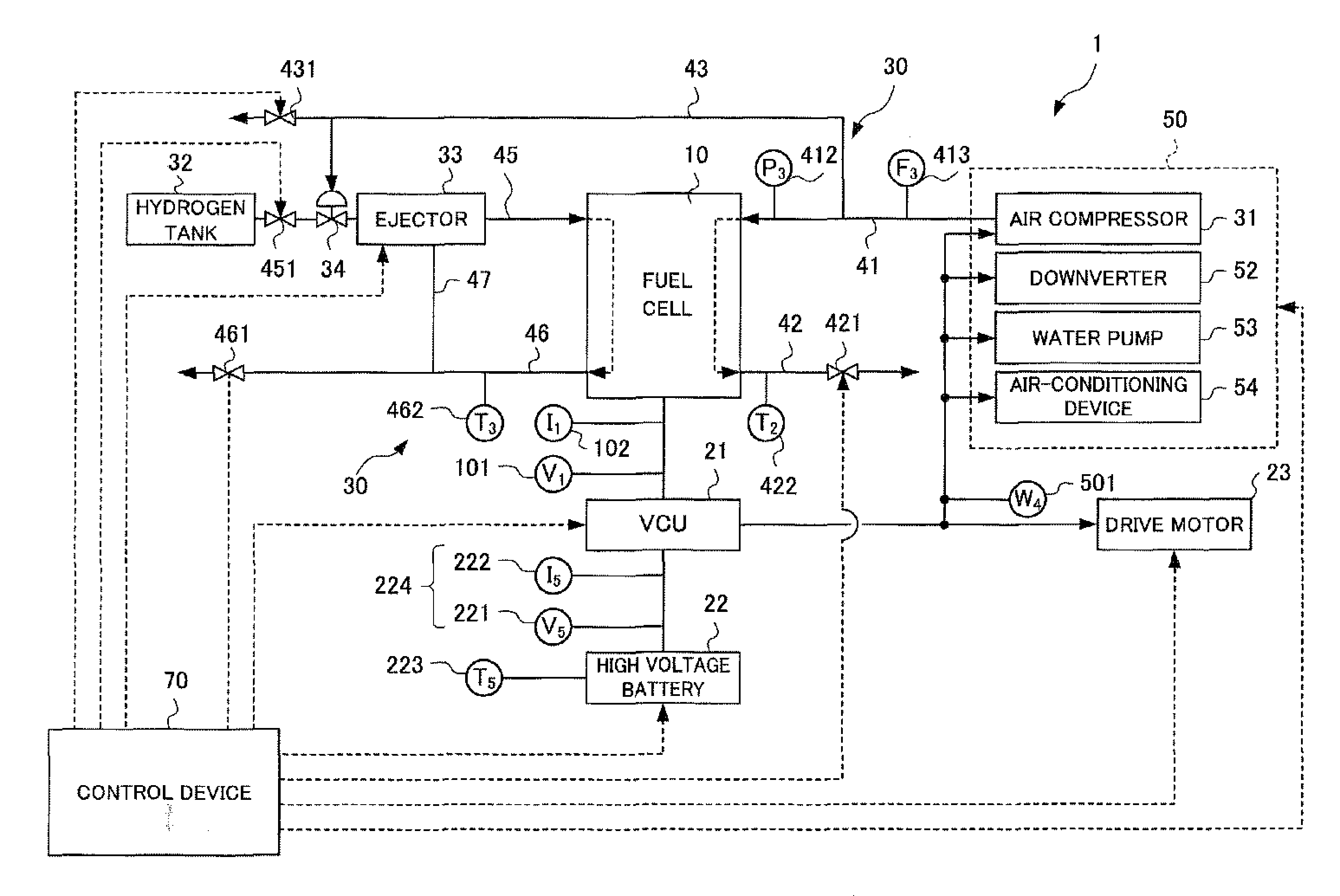
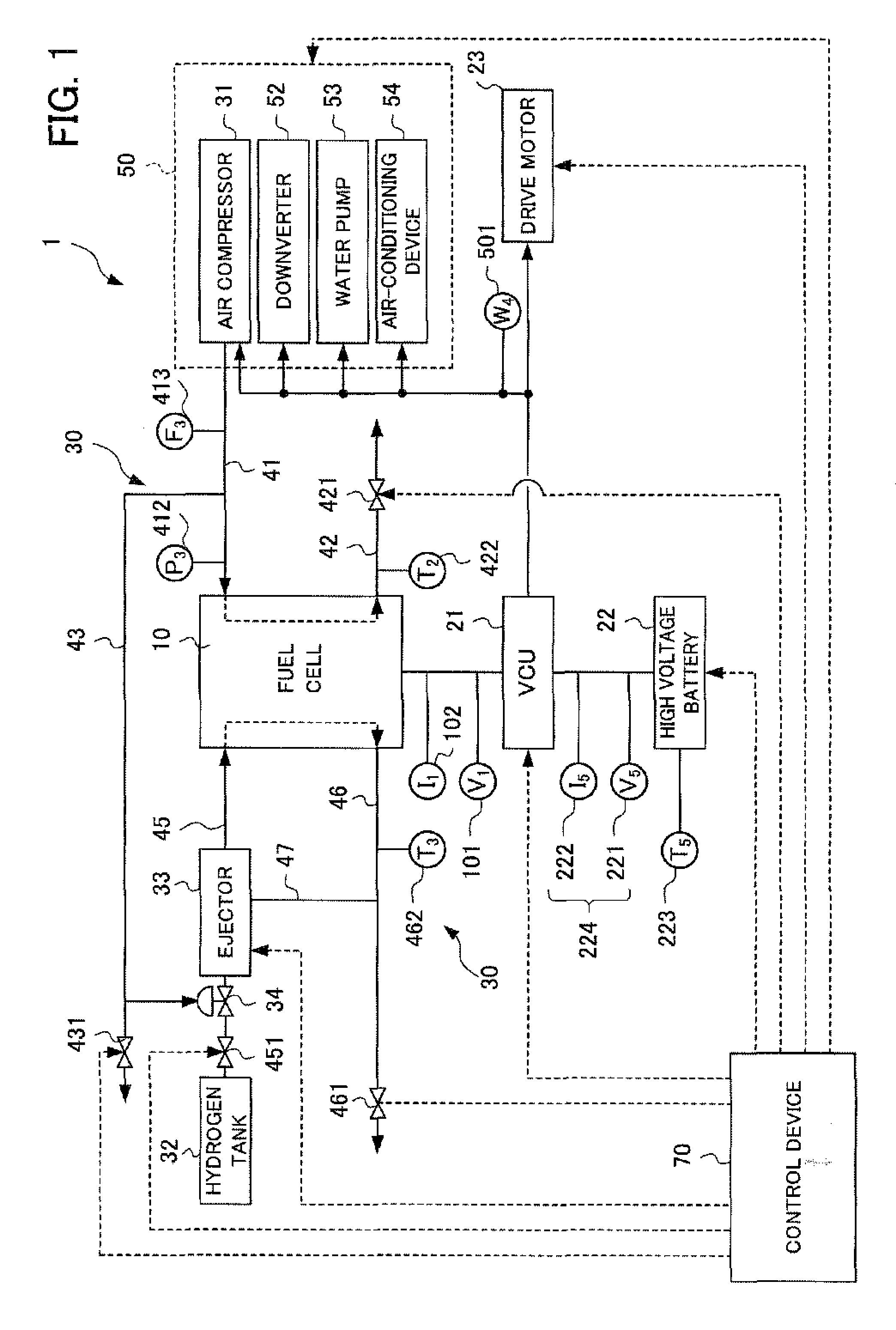
[0040]FIG. 1 is a block diagram of the fuel cell system 1 according to the first embodiment of the present invention.

[0041]The fuel cell system 1 includes a fuel cell 10, a supply device 30 supplying reactive gas such as hydrogen gas and air to the fuel cell 10, an auxiliary device 50 driving the fuel cell 10 and the supply device, and a control device 70 controlling the fuel cell 10, the supply device, and the auxiliary device 50 as the control means.

[0042]The fuel cell 10 can be configured by including a plurality (e.g., tens or hundreds) of stacked cells. In such an example, each cell is configured with a membrane electrode assembly (MEA) placed between a pair of plates. The MEA is configured with two electrodes, such as an anode (i.e., a positive electrode) and a cathode (i.e., a negative electrode), and a solid polymer electrolyte membrane held between these electrodes. Generally, these electrodes are formed from a catalyst layer in contact with the solid polymer electrolyte me...

second embodiment

[0101]In order to omit or simplify the explanation of the following embodiments, the same elements are indicated by the same numerals.

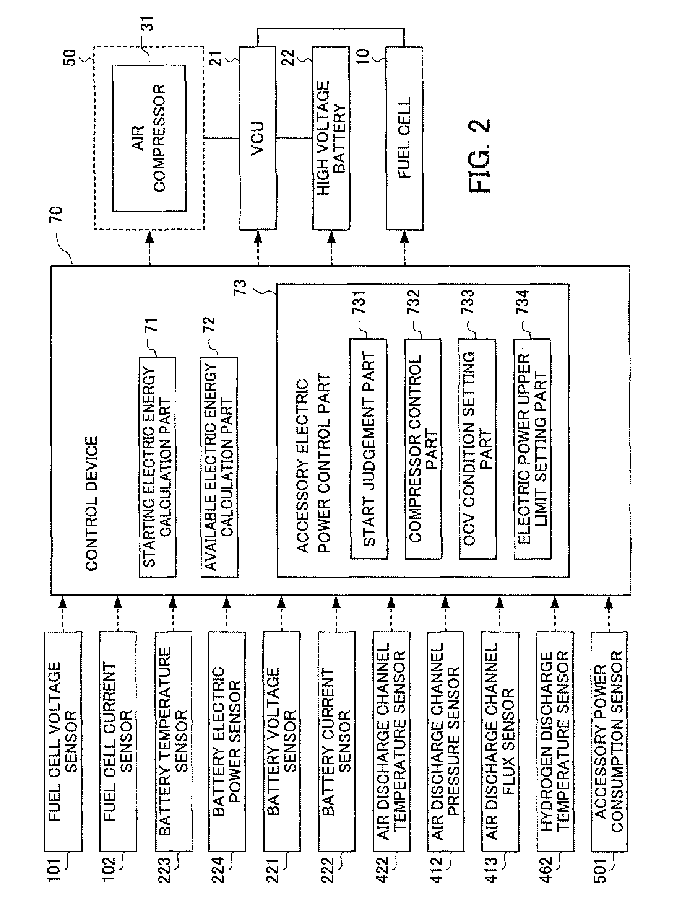
[0102]FIG. 9 is a block diagram of the control device 70A in the fuel cell system 1 according to a second embodiment of the present invention.

[0103]As shown in FIG. 9, the fuel cell system of the second embodiment differs from the fuel cell system of the first embodiment in that the structure of the auxiliary device electric power control portion 73A of the control device 70A. Specifically, the auxiliary device electric power control device 73A is provided with a start judgment portion 731, a compressor control portion 732A, an OCV condition setting portion 733, and a voltage lower limit setting portion 734A.

[0104]In the fuel cell system 1 of the first embodiment, electric power is supplied to the auxiliary device 50 so that electric power drawn from the high voltage battery 22 does not exceed the upper limit of electric power set by the electric powe...


PUM

PropertyMeasurementUnit
temperatureaaaaaaaaaa
temperature T5aaaaaaaaaa

Abstract

The object of the present invention is to provide a fuel cell system enabling reliable startup thereof, even below the freezing point. The fuel cell system 1 is provided with a startup electric power calculation portion 71 for calculating electric power required for allowing an auxiliary device 50 to startup the fuel cell; an available electric power calculation portion 72 calculating the available electric power of the high voltage battery 22; and an auxiliary device electric power control means 73 for judging whether the available electric power exceeds the startup electric power, supplying electric power to the auxiliary device 50 to startup the fuel cell 10 when the available electric power is greater than the startup electric power, and cancelling startup of the fuel cell when the available electric power is not greater than the startup electric power.

Description

[0001]This application is based on and claims the benefit of priority from Japanese Patent Application No. 2007-100783, filed on 6 Apr. 2007, the content of which is incorporated herein by reference.BACKGROUND OF THE INVENTION[0002]1. Field of the Invention[0003]The present invention relates to a fuel cell system. Specifically, the present invention relates to a fuel cell system enabling startup below the freezing point.[0004]2. Related Art[0005]Recently, fuel cell systems have drawn attention as new sources of power that can be used to drive vehicles. For example, a fuel cell system can be provided with a fuel cell producing electric power from chemical reactions of reactive gas, a reactive gas supply device supplying reactive gas to the fuel cell through a reactive gas channel, and a control device controlling the reactive gas supply device.[0006]The fuel cell can be structured to include a plurality, e.g., tens or hundreds, of stacked cells. In such an example, each cell is confi...

Claims


Application Information

Patent Timeline
Patent Type & Authority Applications(United States)
IPC IPC(8): H01M8/04H01M10/46
CPCH01M8/04097H01M8/04223H01M8/04268H01M8/04343H01M8/0435H01M8/04373H01M8/04395H01M8/04559H01M8/04567H01M8/04589H01M8/04597H01M8/04626H01M8/04738H01M8/04947H01M8/04955H01M16/003H01M2008/1095Y02E60/50H01M8/04302H01M8/04225
Inventor WAKE, CHIHIROOGAWA, JUMPEI
Owner HONDA MOTOR CO LTD
Why Eureka
Try Eureka