Receiver Having a Gain-Controllable Stage

Active Publication Date: 2008-10-09
NXP BV
View PDF11 Cites 2 Cited by
  • Summary
  • Abstract
  • Description
  • Claims
  • Application Information

AI Technical Summary

Benefits of technology

[0010]Another advantage of the invention relates to the following aspects. In principle, it is possible to design a filter, which is placed before a gain-controllable stage, that provides a substantially constant source impedance throughout a frequency band of interest, even when the filter is tuned. Such a constant impedance filter would allow a relatively low noise throughout the frequency band of interest for the reasons explained hereinbefore. However, suc

Problems solved by technology

Under such a weak signal reception condition, any receiver noise will degrade a signal-to-noise ratio that is already low because of the relatively weak desired signal.
Under such a strong signal reception condition, the relatively strong desired signal may overload one or more circuits within the receiver, which causes distortion.
Under such a weak-with-strong signal reception condition, the relatively strong signals may generate spurious signals, such as intermodulation products, whi

Method used


Image

  • Receiver Having a Gain-Controllable Stage
  • Receiver Having a Gain-Controllable Stage
  • Receiver Having a Gain-Controllable Stage

Examples


Embodiment Construction

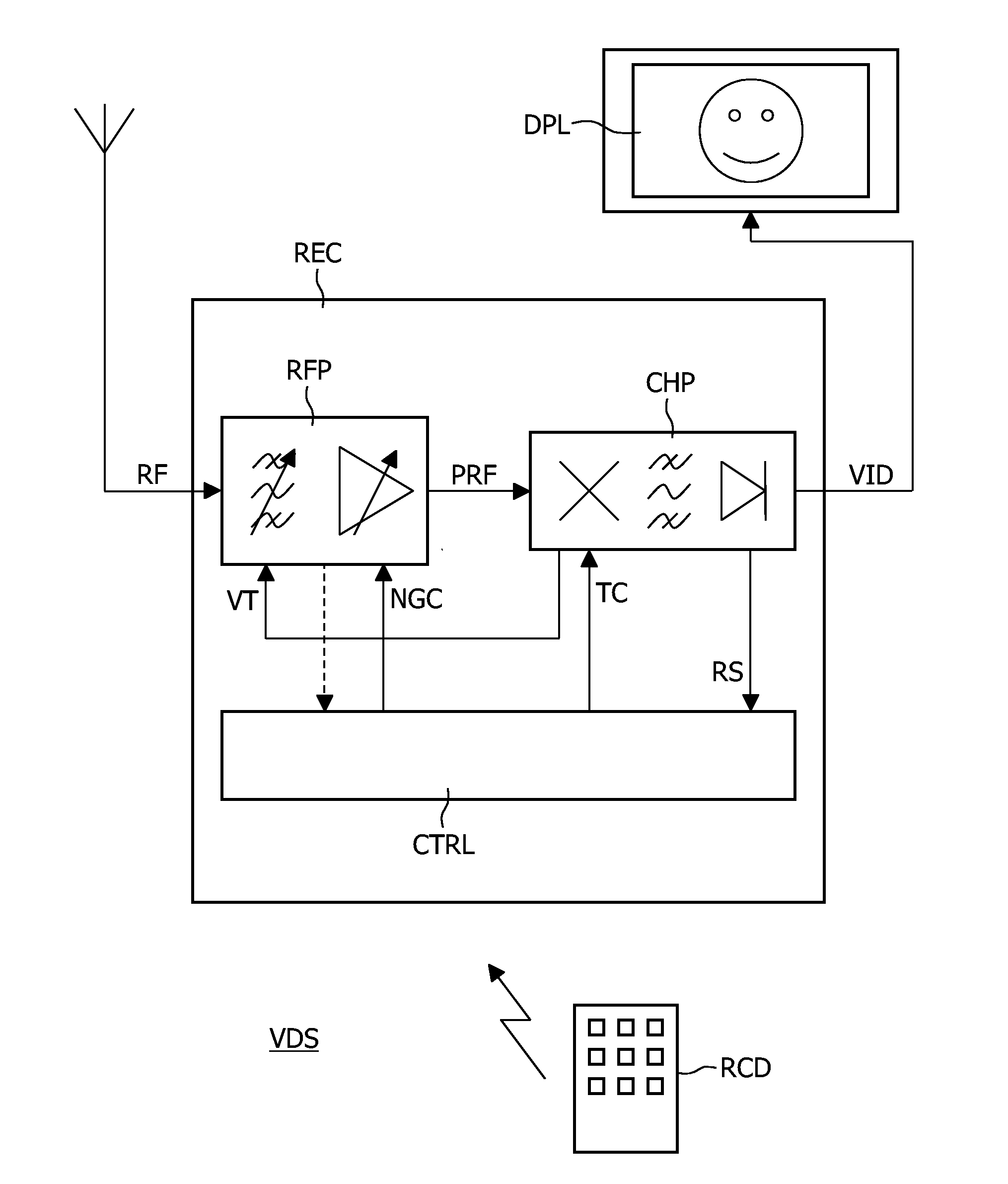
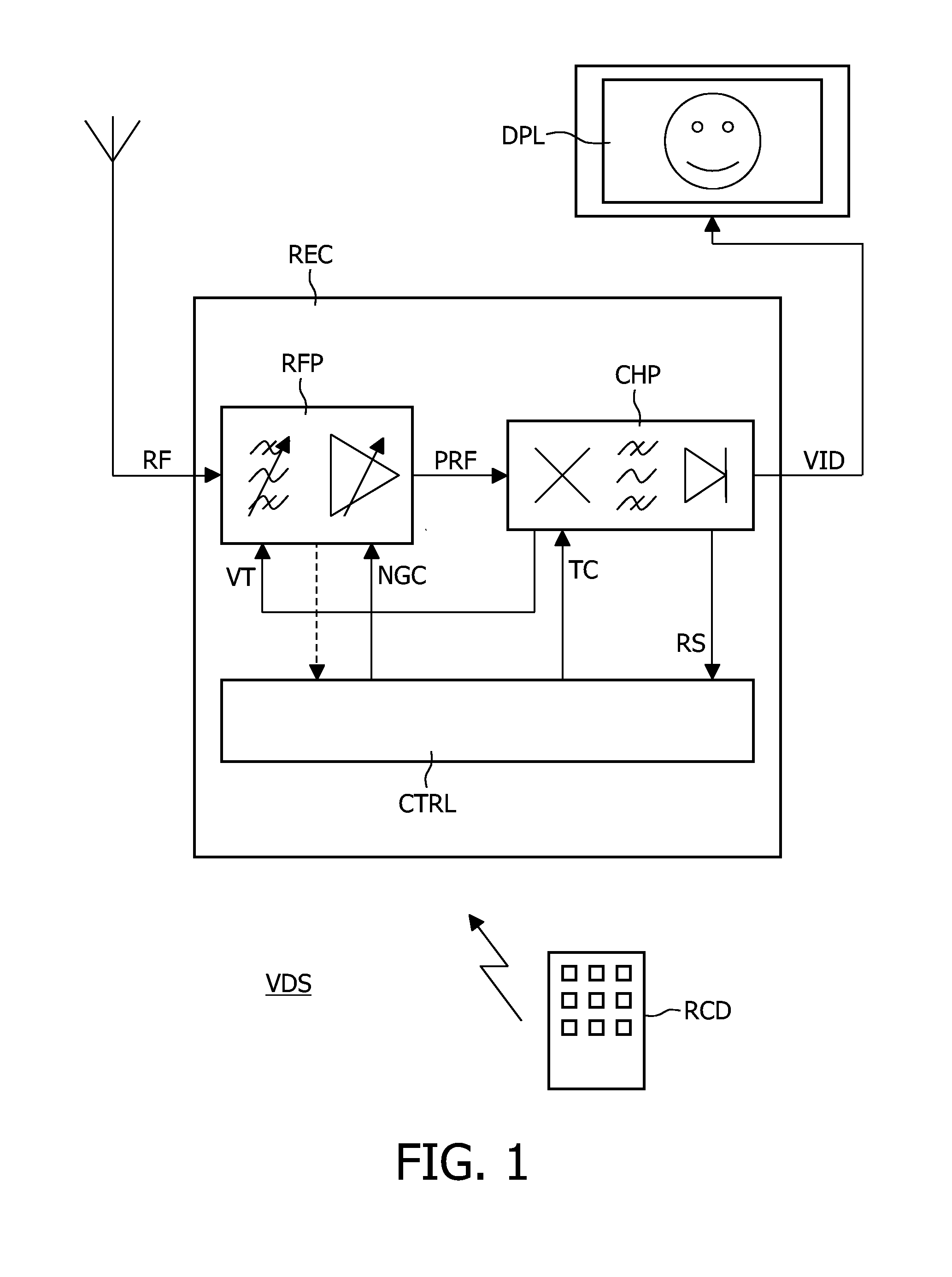
[0020]FIG. 1 illustrates an embodiment of a video display set VDS. The video display set VDS comprises a receiver REC, a display device DPL, and a remote control device RCD. The receiver REC may be in the form of, for example, a television set, a settop box, a digital video recorder, or any combination of those. The display device DPL may be, for example, a flat panel display with loudspeakers. The display device DPL and the receiver REC may form one apparatus or may be separate entities.

[0021]The receiver REC receives a radiofrequency spectrum RF that comprises various channels. Each channel has a different frequency. A user can select a particular channel by means of, for example, the remote control device RCD. The particular channel, which the user has selected, will be referred to as selected channel hereinafter. The receiver REC derives a video signal VID from the selected channel. The display device DPL displays the video signal VID.

[0022]The receiver REC comprises the followi...


PUM


Abstract

A gain-controllable stage (CLN, A1, A2 . . . , A7, ACC) comprises a reactive signal divider (CLN) followed by an amplifier arrangement (A1, A2 . . . , A7, ACC). The reactive signal divider (CLN) may be in the form of, for example, a capacitive ladder network. The gain-controllable stage (CLN, A1, A2 ..., A7, ACC) has a gain factor that depends on a signal division factor that the reactive signal divider (CLN) provides. The reactive signal divider (CLN) forms part of a filter (LC). The signal division factor is adjusted on the basis of a frequency (F) to which the receiver is tuned and a signal-strength indication (RS).

Description

FIELD OF THE INVENTION[0001]An aspect of the invention relates to a receiver that has a gain-controllable stage. The receiver may be, for example, a television receiver that derives video, audio, and other data, from a selected channel in a radiofrequency spectrum. In such a receiver, a gain-controllable stage typically brings the radiofrequency spectrum at an appropriate signal level for further processing. Other aspects of the invention relate to a method of controlling a receiver, a computer program product for a receiver, and an information-rendering system.DESCRIPTION OF PRIOR ART[0002]U.S. Pat. No. 6,272,330 describes a gain controlled radio receiver for a selective call system. The receiver includes a multi-step gain controlled radiofrequency amplifier with various gain stages whose outputs are coupled to a common output stage. A capacitive ladder attenuator is coupled to an input terminal and has various outputs coupled respectively to an input of each gain stage, except for...

Claims


Application Information

Patent Timeline
IPC IPC(8): H04B1/00
CPCH03G3/3052
Inventor BREKELMANS, JOHANNES
Owner NXP BV
Why Eureka
Try Eureka