Arthrodesis of Vertebral Bodies

a technology of vertebral bodies and spacers, applied in the field of intervertebral spacers, can solve the problems of increasing pain, blood loss, and trauma to patients, and reducing the service life of patients, so as to prevent the migration of spacers

Inactive Publication Date: 2008-10-09
SCHOEDINGER III GEORGE R +1
View PDF28 Cites 2 Cited by
  • Summary
  • Abstract
  • Description
  • Claims
  • Application Information

AI Technical Summary

Benefits of technology

[0024]After formation of the graft bed, the vertebral bodies are distracted. While the vertebral bodies are distracted, the spacer is inserted into the graft bed and positioned so that the flanges are adjacent the furrows in the end plates. Thereafter, upon releasing the distraction, the vertebral bodies will move toward each other and the flanges will be pressed into the furrowed portions of the end plates. The effect of such pressing action is to secure the spacer tightly in place within the graft bed such that migration of the spacer is prevented.

Problems solved by technology

However, the use of substantially sized bone grafts can add complications to the fusion procedure.
For example, when using an autologous bone graft, a second incision must be made in the patient to harvest the additional bone to be used in the graft, thus increasing the pain, blood loss, and trauma to the patient.
When allogenic or xenogenic bone grafts are used there is a potential for the transmission of disease from the cadaver or other graft source to the patient.
Unfortunately, it is difficult and time-consuming to create a graft bed during the course of a surgical procedure that precisely conforms to the size and shape of a pre-existing spacer whose dimensions cannot be changed.
Since it takes about two months or more after implantation of a spacer for sufficient tissue ingrowth and bony fusion to occur, any post-operative migration of the spacer could extend the healing process or possibly render the spacer ineffective for its intended purpose.
The problem of migration also exists with respect to cylindrical or truncated conical spacers.
While the use of such spacers is desirable because it is relatively easy to form a graft bed by drilling, post-operative migration remains a problem.
While the referenced patents attempt to address the problem of spacer migration, it is believed that the shape of the spacers and the configuration of the fins are not an optimum approach to solving the problem.
In addition to post-operative migration, a number of difficulties still remain with many of the spacers currently available.
While it is recognized that a hollow spacer containing bone or bone substitute disposed within the implant is a desirable technique for achieving fusion, some of the prior art devices have difficulty in achieving this fusion, at least without the aid of some additional stabilizing device, such a rod or plate.
On the other hand, the bone ingrowth openings must not be so large or extensive in number that the spacer does not have enough structural integrity to support the heavy load and bending moments that will be applied to it.

Method used


Image

  • Arthrodesis of Vertebral Bodies
  • Arthrodesis of Vertebral Bodies
  • Arthrodesis of Vertebral Bodies

Examples


Embodiment Construction

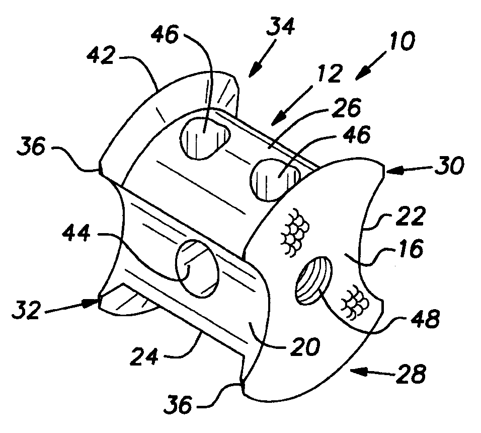
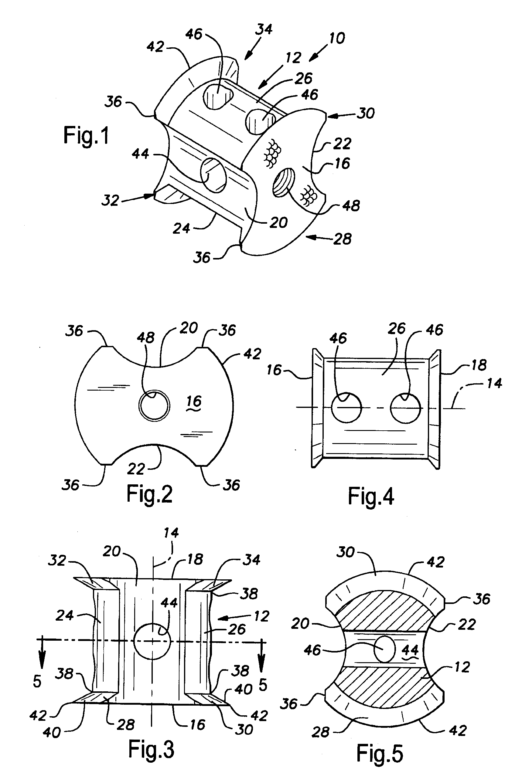
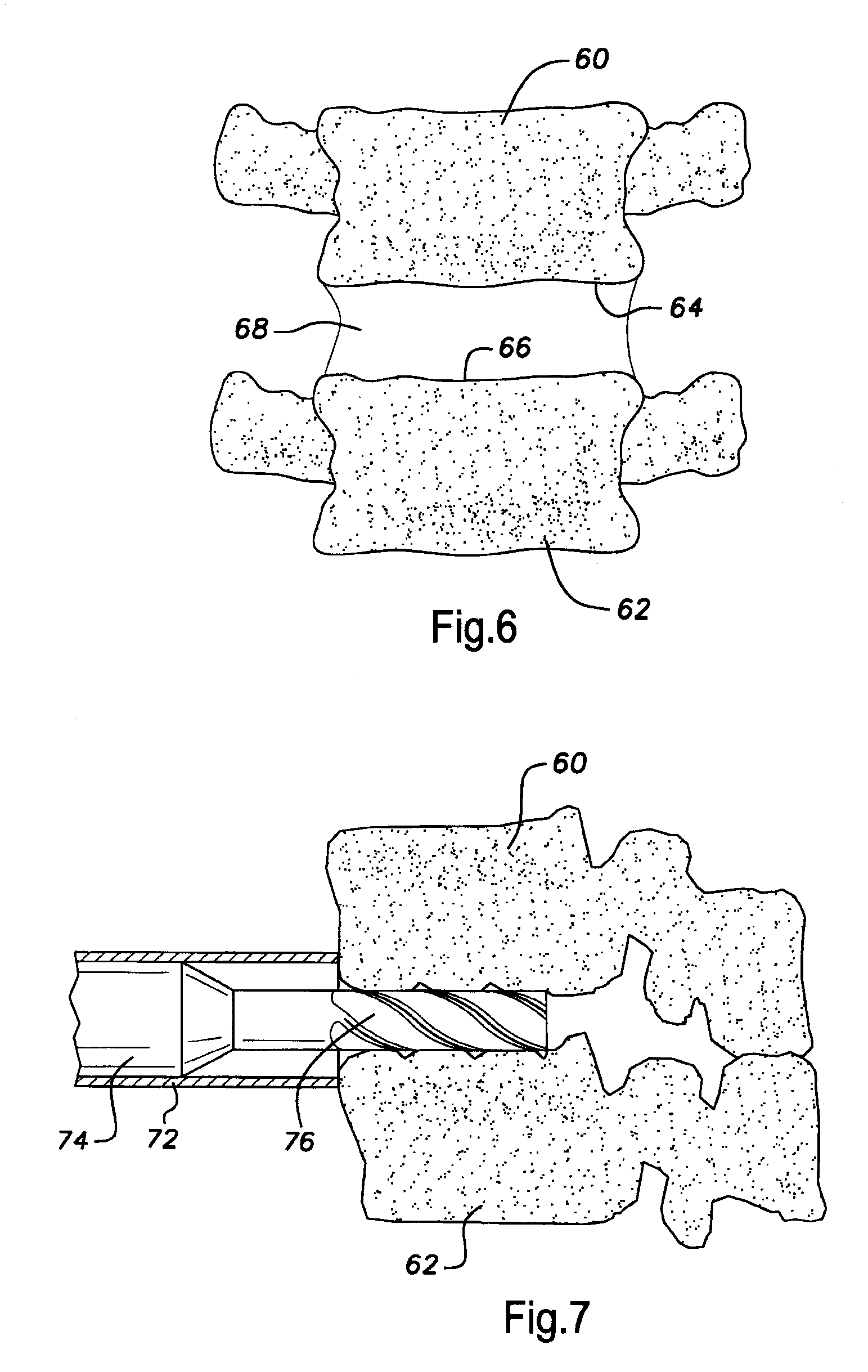
[0037]Referring to FIGS. 1-5, an intervertebral spacer in accordance with the present invention is indicated by the reference numeral 10. While the specific example of the intervertebral spacer 10 described herein is with reference to arthrodesis of vertebrae of the lumbar spine and the sacrum, the invention also applies to arthrodesis of vertebrae of the cervical and thoracic spine. Moreover, although the spacer 10 preferably is installed through an anterior approach to the spine, the spacer 10 also could be installed through a posterior approach to the spine, if desired.

The Spacer 10

[0038]The spacer 10 includes a body portion 12 having a longitudinal axis 14 and anterior and posterior end faces 16, 18, respectively. The spacer 10 is symmetrical about transverse and lateral planes taken through the center of the body portion 12. Thus, either of the faces 16, 18 could be denominated the anterior face or the posterior face. In the embodiment illustrated, the end faces 16, 18 are flat...


PUM


Abstract

Spinal arthrodesis is accomplished by implanting an intervertebral spacer made of a biocompatible material that promotes tissue ingrowth and bony fusion. The spacer is implanted into a graft bed formed between adjacent vertebral bodies. The spacer includes a body portion having anterior and posterior end faces. Opposed flanges project outwardly from the body portion at axial locations adjacent the anterior and posterior end faces. The flanges taper radially outwardly to an outer edge that is sharp enough to penetrate vertebral end plates. After a graft bed has been formed, and after the vertebral bodies have been distracted, the spacer is inserted into the graft bed and positioned such that the flanges are adjacent the vertebral end plates. Upon release of the distraction, the vertebral bodies will move toward each other and the flanges will be pressed into the end plates. The effect of the pressing action is to secure the spacer tightly in place within the graft bed such that migration of the spacer is prevented.

Description

BACKGROUND OF THE INVENTION[0001]1. Reference to Related Patents.[0002]Reference is made to U.S. Pat. No. 5,961,554, issued Oct. 5, 1999 to Frank S. Janson and Albert N. Santilli; U.S. Pat. No. 6,572,619, issued Jun. 3, 2003 to Albert N. Santilli; U.S. Pat. No. 6,572,654, issued Jun. 3, 2003 to Albert N. Santilli; and U.S. Pat. No. 6,673,075, issued Jan. 6, 2004 to Albert N. Santilli (collectively “the Porous Spacer Patents”), the disclosures of which are incorporated herein by reference.[0003]2. Field of the Invention.[0004]The invention relates to the arthrodesis of vertebral bodies and, more particularly, to an intervertebral spacer that will not migrate within its graft bed, thereby promoting rapid arthrodesis.[0005]3. Description of the Prior Art.[0006]Techniques and devices for fusing two or more vertebrae of the spine together are well known. Such techniques commonly are performed to correct problems, such as chronic back pain, which result from degenerated intervertebral dis...

Claims


Application Information

Patent Timeline
Patent Type & Authority Applications(United States)
IPC IPC(8): A61F2/44
CPCA61F2/3094A61F2/446A61F2/4611A61F2002/3013A61F2002/30574A61F2002/30769A61F2002/30787A61F2002/3092A61F2002/30968A61F2002/4495A61F2002/4627A61F2002/4629A61F2230/001A61F2310/00011A61F2310/00203A61F2310/00239
Inventor SANTILLI, ALBERT N.SCHOEDINGER, GEORGE R.
Owner SCHOEDINGER III GEORGE R
Why Eureka
Try Eureka