Extruded Structural Beam

Inactive Publication Date: 2008-10-16
HALL BRIAN +1
View PDF12 Cites 8 Cited by
  • Summary
  • Abstract
  • Description
  • Claims
  • Application Information

AI Technical Summary

Benefits of technology

[0017]Another object of the present invention is to provide an improved structural beam that has interlocking flanges to increase the strength of the beam.
[0018]Another object of the present invention is to provide an improved structural beam with two separate members that act as one unit and to decrease the likelihood of local buckl

Problems solved by technology

Although a beam with a larger cross section provides additional, strength and can span larger distances, a disadvantage to a larger beam is that it is not aesthetically pleasing, is heavy in weight making it more difficult to wo

Method used


Image

  • Extruded Structural Beam
  • Extruded Structural Beam
  • Extruded Structural Beam

Examples


Embodiment Construction

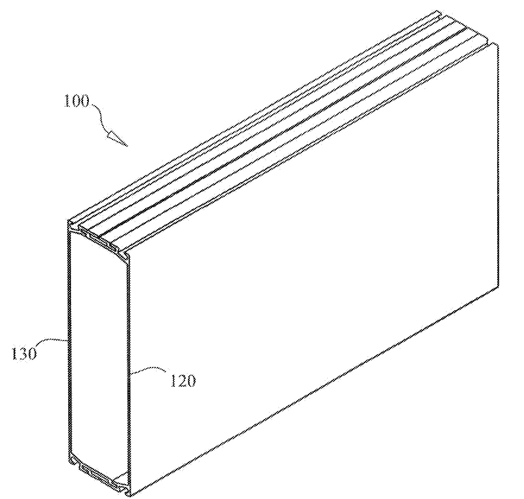
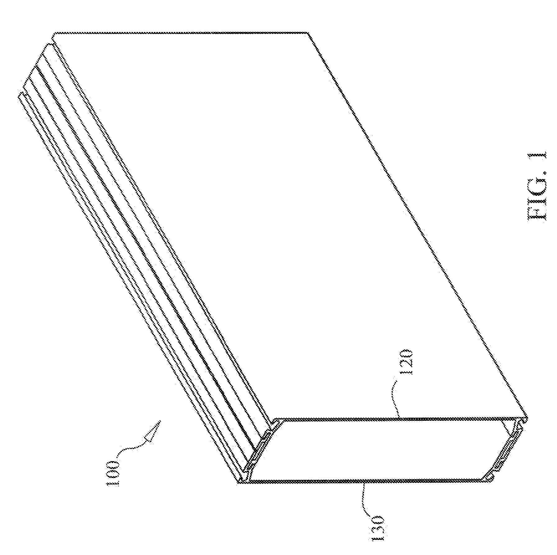
[0036]FIG. 1 shows the new beam 100 is comprised of a first member 130 and a second member 120. The beam 100 is shown assembled to form a rectangular hollow shape. Each member is a standard beam shape that is used in construction, of screen enclosures and extruded through a die process to various lengths. First member 130 and second member 120 are assembled in the field to form the new structural beam 100. The materials used to make beam 100 are the same aluminum alloys that are used in the construction of aluminum, screen enclosures. The wall thickness of first member 130 and second member 120 will vary between each size change and are dependant on code requirements to meet deflection criteria in the local and state building codes.

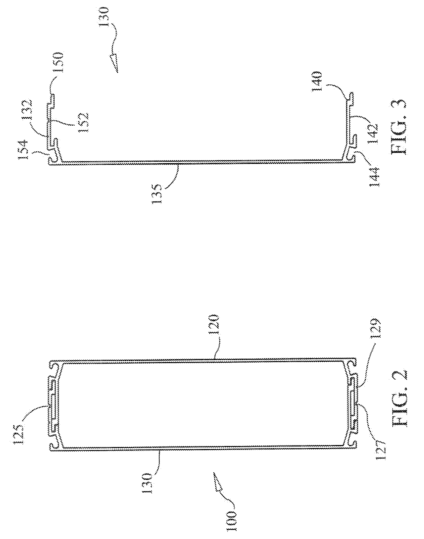
[0037]Referring now to FIG. 2 and FIG. 3, a cross section of the beam 100 is shown including the coupling of the flanges. A longitudinal slot 125 on top flange 150 and longitudinal slot 127 on bottom, flange of second member 120 show where screws are used...


PUM


Abstract

An extruded structural beam having a first member comprising rigid webbing interposed between a top flange and bottom flange. The top and bottom flanges of the first member each have a groove formed thereon for receiving a spline to secure screening material. Similarly, a second member having rigid webbing interposed between a top flange and bottom flange have a groove formed on the flanges for receiving a spline to secure screening material. The top and bottom flanges of both the first member and second member each further comprise opposing longitudinal channels for coupling the flanges so that a rectangular structural beam is formed. The outer surfaces of the flanges each further comprise a longitudinal slot so that a plurality of fasteners can be installed, through the longitudinal slots and flanges to secure the first member and second member together.

Description

BACKGROUND OF THE INVENTION[0001]1. Field of the Invention[0002]The present invention relates generally to structural beams, and more specifically to using a novel means of assembly and flange design to increase the strength, of a structural beam.[0003]2. Description of the Prior Art[0004]It is common for lightweight aluminum alloy beams to be used to construct the framework for a screened pool enclosure. The beams are typically assembled in the field from two separate members to form a hollow box beam. The distance that the aluminum beam can span over an open space without additional support is determined by the thickness, or gauge, of the aluminum. Another factor is dimensions of the beam. Although a beam with a larger cross section provides additional, strength and can span larger distances, a disadvantage to a larger beam is that it is not aesthetically pleasing, is heavy in weight making it more difficult to work with in the field and more expensive.[0005]There have been attemp...

Claims


Application Information

Patent Timeline
IPC IPC(8): E04C3/10
CPCE04C3/06E04C2003/0413E04C2003/0439E04C2003/0465
Inventor HALL, BRIANARMSTRONG, JIM
Owner HALL BRIAN
Why Eureka
Try Eureka